Since wheels vary so extensively in size, shape, contour, details, axle types and mounting methods, each case may be quite different. Square axle alignment is very critical to prevent wobble which will definitely show in and effect operation. Correct gauging is absolutely essential for good operation through frogs and other complex trackwork. The most important tool any serious modeler should have is an NMRA STANDARDS GAUGE to check or set gauge while mounting wheels.
 CAVEATS:
- If present , avoid any stress on tires, which could cause
misalignment .
- On cast, detailed drivers, all pressure should be on the hub only.
Avoid any stress on other parts which may mar surfaces or crack casting.
- To maintain centering on extended end axles, all force on the opposite
end should be applied to the axle and not the wheel.
- Observe original mounting very carefully and use any knowledge gained during removal as an aid to avoid damage and to attain correct remounting.
Probably most wheel mounting applications are done best using SCREW PRESS or MODIFIED MACHINIST'S VISES with APPROPRIATE TIPS at both ends. Pins can be mounted in screw or arbour press fixtures, or chucked in a squarely aligned drill press.
Although arbor presses are faster, in general, they do not permit final gauging as easily, due to possible overshooting. If used, pressing should be stopped short of the gauge point. Final gauging is best done by light tapping on the axle with a drift pin, but devising a suitable backup fixture with good alignment may be very tricky. Another problem that often arises with smaller wheels, is fitting the gauge into the clearance around the press.
Mounting plain diesel, traction and rolling stock wheels is usually much easier than other types. Often usable hubs may be absent or too small, but pressure may be applied to rims, which normally run true with flanges.

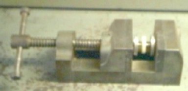
Mounting wheel on needle point axle with frame press.
Notice pin pushed out on spring. Both pins have tips for tapered axles. Pressure is applied to the rim of the brass wheel on the left. However with small wheels the gauge can not be used, necessitating removal to check.

Mounting wheel on needle point axle with rectangular tube press.
The set screw backup is adjusted to allow tube side to enter notch and permit gauging.
For wheels with detailed centers or tires, such as spoked pilot and trailing or older traction wheels, pressing is best done at the hubs to avoid damage or misalignment and damage.
For those with extended axles, pressing should be done with tip bored to fit over the axle and an outside diameter which avoids any pressure on driver center details.
Larger drivers present particular problems based on types, sizes or mounting methods. Most have raised hubs, but some also may have crank pin bosses that require special tooling. Others may have splines, knurling, keys or flats which must be lined up before mounting. WITNESS MARKS, scribed before pulling, are great aids here.
CAVEAT: Since they often have
delicate detail and are cast in softer, perhaps brittle materials, drivers
deserve special treatment, especially those with crank pin bosses. They are
relatively thin, increasing the probability of misalignment wobble upon
mounting. Here the proper CHAMFERING OR
ROUNDING of newly cut axle ends is extremely important. Sharp
ends may act as chisels, cutting away the walls, thus destroying the bore,
preventing alignment. If not already done, the insertion edge of the driver
bore should be chamfered with an angular countersink or burr. NWSL's
catalogue and some tool instructions cover this very thoroughly. Before
using vise corners to press on hubs, determine that all other parts
clear jaw faces.

Using corner of machinist's 's vise to press plain raised hub, flush axle (Penn-Line GG-1) aids careful eyeball alignment.

Using a quartering jig in a machinist's vise to press plain, flush axle, drivers can eliminate the necessity of special pressing pins and aid alignment.
QUARTERING
Prototype drivers with siderods always have crank pins on opposite sides quartered (set at right angles to each other) to avoid starting dead spots in the engine cycle. Models follow the practice for appearance sake and smoother force transfer through the siderods, using various methods for alignment.
Before driver removal, examine closely for their presence. Some use a single spline or key, while Rivarossi uses a number of matching splines around the axle and the driver bore. In any case apply a WITNESS MARK by lightly scribing a line across the driver center boss and axle juncture to guide mounting realignment. The witness mark here will not only assure proper quartering but help avoid ruining the soft plastic bore splines.
CAVEAT: Since Rivarossi
drivers (some AHM) have plastic centers and axles have splines, _DO
NOT_ use quartering jig crank pins. Use only witness mark as guide
and be sure splines enter grooves easily before applying any pressure.
Damage may not be repairable. Those with flats or keys are handled the same
way.
Since most manufacturers do not go to the extra expense of using splines, a quartering jig is necessary to remount squarely. Makers are only concerned that all their drivers have the same right angle, whether it is 90 or 89 degrees. And since all quartering jigs are not created equal, due to machining tolerances or wear, requarter all drivers so they are the same.
Three and a half jigs have been used over the years. My favorite is the Dean Downer Associates MULTI-VISE, a modified machinist's vise from the 50's. One of its major advantages is the capability to handle any combination of bearings and off center axle gears, used in compound gearing. It has centered bores which accept bushings with bores for pins of various axle diameters of an easy fit. The pins support drivers until pressing starts and recede as it continues. The bushings do the pressing and are modified to avoid side rod bosses and crank pins on smaller drivers .
CAUTION: Pressing on side rod bosses or
raised spacers during any stage can introduce wobble.
Perpendicular slots through the centers of each face accept headless crank pins snugly, for excellent quartering. Just before gauge is reached, final pressing is done at a corner of the faces, again avoiding those bosses. To avoid overshoot, pressing is done very slowly, checking each slight press with the gauge.
Using a MULTI-VISE to quarter drivers. Crank pins are not visible.
Final gauging is as shown above,
The other two and a half JIGS were from NWSL and all of the same basic design. Two body plates fit tightly on two rods perpendicular to them with spacer(s) to provide a slot for a gear. Centered between the rods, each plate has an axle slot with a nylon screw to clamp the axle. On either side, a quarter plate slides snugly onto the rods each having a pressing pin and two index surfaces upon which are aligned. Pressing is done with an arbor press, drill press or a solid vise. The vise is the best choice since better control can be attained because of the screw thread ratio.
The first or half jig, of aluminum, had only one quarter plate and a blank plate. To complete the job, the plates were exchanged. The second was identical except it had two quarter plates to make things easier. In the third, all aluminum parts are replaced with what appears to be delrin. One improvement is a wider range of crank pin radii can be accommodated both larger and smaller. They all work very well, following the instructions which are very complete. The last is the only one still manufactured.

Using a quartering jig in a MULTI-VISE to press and quarter drivers. Note crank pins. Gauging is as shown above.
CAVEAT EMPTOR: Do not be impressed with
sales pitches at "shows" about the most accurate jig ever available to the
hobbyist at over three times the cost. Precision 90 degrees is not the
criterion, but repeatability on all drivers, connected to the same siderods,
is.
BACK TO GEAR MOUNTING END
BACK TO MANTUA PLASTIC CAMELBACK
BACK TO METHODS
