Discovering two of these as basket cases, at a flea market, with a price lower than the original $15 each; they were snatched-up. Although not very detailed, they were complete (kits). But the zamac driver centers had expanded, splitting most of the tires. There was even a gear box and flywheel.
Note: Adjust brightness and contrast for optimum viewing.
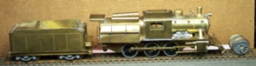
Ready for track testing w/ new 62" drivers mounted.
Original driver with split tire.
After disassembly the drivers were measured, with the driver diameter at 66" and the axles at 4 mm. On close prototypes, the Reading used either 61" for fast freight or 68.5" for passenger service. One would be done in each size. After very difficultly removing one of the frozen driver screws, the wheel shoulders were found to be 3 mm. Buying new drivers, bored this size, from Greenway, at $16 per pair, was not very appealing.
Having Bowser unmounted 62" and 69" rivers on hand in our stock, various ideas were kicked around to match their 1/8" axles to the frame's 4 mm slots. Bowser's square bushings fit the .040 side rails nicely, but the OD was too small and would require delicate shimming. Other bearings would not fit without machining.
Since K & S 5/32" OD, brass tubing has a 1/8" ID; this was tried for fit. As 4 mm = .15748 and 5/32 = .15625", the difference is just over .001". Bowser's 1/8" axles fit well inside. This provides bearings similar to Mantua's, but slightly tighter. Two were cut to the frame width for the outer drivers and ends were carefully deburred. Then the axles were pushed through and drivers were mounted and quartered. The drivers were placed in the slots and the cover plate was bent to press these in the slot arched tops to center them and prevent rotation. The siderods were mounted with Bowser 720 crank pins, but there was some bind due to rod thickness. A diamond nail file was used on the backs of the rods to thin them for free rolling on track.
NOTE: Some newer Bowser driver set axles have spline knurling at ends, which serves as a guide for mounting. These eliminate the need of a quartering jig. However be sure to make witness marks before pulling to assure correct alignment.
The original motor shaft passed through a hole at the top of the gear box. The flywheel was mounted on the outside, leaving a small space between it and the worm. This held the box in alignment without thrust washers. Fortunately the motor mount was pivoted at the side rails to adjust mesh. On one loco, it was screwed; while on the other it was riveted. The latter could be pried into position.
It was decided to keep the original gear box. At first the axle gear was to be mounted on a short length of tubing and secured to the axle with Lock-tite and use two lengths on either side for bearings, but during trials this produced too much wobble. At the risk of wear, a single length was cut to frame width and cleaned. The tube was pushed through one side of the box, through the gear an out the other side of the box. The gear was carefully centered and secured with Lock-tite Red.
Note: Adjust brightness and contrast for optimum viewing.
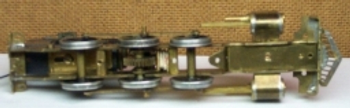
Brass tube bearings.
When set up, the assembly was mounted in the frame and the motor was mounted to check mesh. When satisfied drivers were mounted and side rods were connected with Bowser 721 crank pins and then tested.
Track testing with 62" drivers and original motor yielded over 140 SMPH, so a Pittman DC-60 was substituted for fit. The flywheel did not fit well, vibrated excessively and so was left off. This left the top of the gear box move to and fro, creating erratic mesh. A small block of lead was cut and wedged between it and valve gear hanger, vertical mount bar. Placing the boiler shell on frame, shorted the motor brush tops. These were ground down to the curved section, still providing good spring purchase. Track testing went well, but speed was about 99 SMPH. Replacing the alnico magnet with neodymium, brought the speed down to about 70 SMPH.
The second was done with 69" drivers and clocked at about 79 SMPH. A minor problem was to replace the obnoxious, white 30" pilot truck wheels with black 33". With some weighting, modifications and detailing these will be believable additions to the stable.
