|
|
| Home |
| PPD |
| Sites |
| ABdA |
| Help |
|
WEEK 07: TRANSMISSION: COMPONENT SPECIFICATIONS Sections: Transformers | Circuit Breaker | Switchgear | Switchers | Fuses Circuit switchers are mechanical switching device suitable for frequent operation; not necessarily capable of high-speed reclosing; capable of making, carrying, breaking, or changing the connections in an electrical circuit, under either normal or abnormal conditions. They include all types of switches, fuses and a large number of other devices. Principal designating parameters are (a) maximum operating voltage (applied to 72.5 to 242 kV, with special applications at 362 and 550 kV), (b) basic insulation level (BIL), (c) rated load current (capable of handling 4 to 16 kA short-circuit current on a symmetrical basis; continuous current ratings are 1200, 1600, and 2000A), (d) interrupting current (interrupting time is the maximum permissible interval between energizing the shunt trip coil at rated control voltage and the interruption of the main circuit in all poles when interrupting a current within the required interrupting capabilities), (e) duty cycle (the short-circuit current to be interrupted, closed upon, etc.), (f) Corona-RIV (a corona-free rating is commonly established to prevent radio and television interference, known as radio influence voltage and should be less than 500mV); (g) whether an isolator and/or a trip device is required, and (h) whether manual or motorized operation is required. Definition. Switches are electrical devices which are manually moved to either ON or OFF positions. Classification. A. Knife Switches An open-type switch consisting of a movable knife blade, a pivot and a mount. They are extensively used in lighting and small power circuits, with proper fuses connected in series with the switch blades. Knife switches must be "dead" in open position, i.e., gravity cannot tend to close an opened switch (upside down). The supply line must be on top while the load-side must be at the bottom or the pivot part of the switch. When enclosed, a minimum gutter space must be at least four (4) inches and the wire-bending space at terminals must be six (6) inches minimum.
B. Disconnecting Switches A knife switch connected in series with a circuit breaker used on power circuits. Connect the switches in such a manner that when opened the blade will be "dead". Disconnecting switches should never be opened until the circuit breaker in the same circuit has been opened, and should always be closed before the circuit breaker is closed. They are not designed to break currents and should, therefore, never be opened while current is flowing in the line. These switches are designed to carry expected load currents and remain closed for momentary current flow such as fault currents. Fault currents in excess of a specific rating may cause the switch to be blown open by the magnetic forces due to the short-circuit current. They should be used on both sides of the circuit breakers, to deaden both side of the breaker for repairs or replacements purposes. Disconnecting switches are used primarily for isolation of equipment such as buses or other live apparatus. They are used for sectionalizing electric circuits such as buses or lateral circuits or even portions of main feeders for special purposes such as testing and maintenance.
There are three classes of disconnect switches: (1) Station, (2) Transmission and (3) Distribution. Switches are further categorized as gang- or hookstick-operated and loadbreak and non-loadbreak types. The basic insulation level (BIL) of station-class equipment is normally higher than for transmission or distribution equipment. Station equipment ranges from 2.4 to 765 kV. They could be rated up to 3000 A. Manual or automatic switching is also provided. Transmission disconnecting switches are generally used as load-management tools. Load management is achieved during dead time by switching the proper disconnects automatically through sensing loss of voltage. These systems are available through 16 kV, 1200 A. Distribution disconnecting switches provide for both single- and three-phase sectionalizing. They are usually applied on poles.
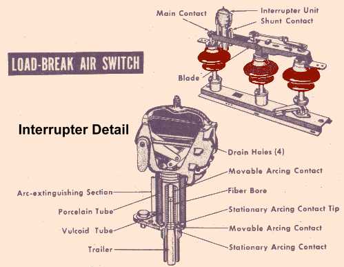
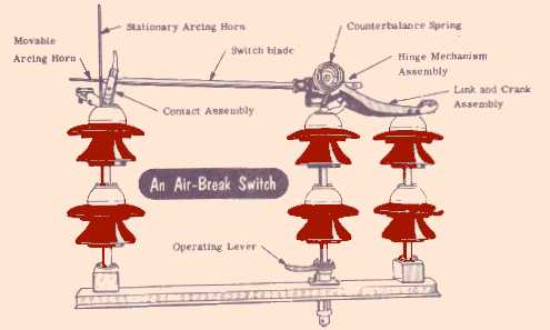
C. Air-Break Switches are designed to open circuits under load. Generally used outdoors for circuits of medium capacity, such as lines supplying an industrial load from a main transmission line or feeder. Air-break switches are built for about 135,000 volts maximum, but their use is in general confined to lower voltages. D. Control Switches include all switches that are used to control the operation of other equipment. They are designed for operating voltages less than 250 volts and very small current capacities, usually mounted on switchboards. Types of Control Switches: 2. By construction / design 3. By function/purpose
b. Protection - switches that guard a branch circuit or from overloads. E. Auxiliary Switches all switches or contactors that are actuated, or electrically operated, by some other control switch or device. The control switch is usually located at any desired distance from the circuit breaker. F. Miscellaneous Switches include oil switches and magnetic-impulse switches. Oil Switches are for certain applications at high voltages and large current capacities. Usually the switch contacts are immersed under oil. The oil cools and quenches the arc that tends to form when the circuit is broken. Magnetic-Impulse Switches is a type of switch where the arc is extinguished by blowing it magnetically into arc chutes where it is lengthened, cooled and interrupted. The magnetic effect is produced by the circuit current which is passed through suitable coils, setting up a strong magnetic field across the space between the switch contacts as they are opened. The basic principle involved in lengthening the arc is that the force is directly proportional to the product of magnetic flux and current. |