Back to Part 2
Head (Neck part 2)
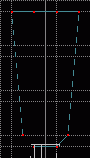
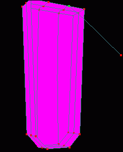
Create a new patch_obj but do not rename it. Switch to a Front view, Zoom out and draw the outline of the top of the neck as the new patch_obj. It should be about twice as tall as the hole of the guitar. Change Grid Size to .25 and select Grid Lock - All for easier placement. The head should be about 12 grid spaces tall with the base being about as small as the end of the neck. Select - None and use the  Free Hand Select tool to draw a selection shape and select the two end points of the upper portion of the head outline. Click the
  Scale tool and scale these points inwards slightly along the X-axis for half a grid space.
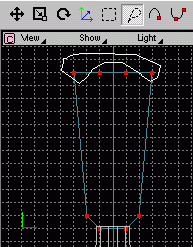
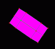
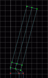
 Switch to a Right view, Select - All and Translate the outline along the Z and Y axes until it lies about one grid space directly above the neck. Extrude the outline along the Z-axis two times, placing each extrusion 1 grid space apart.
 Switch to a Perspective view, Show - Point, - Curve, and - Surface then connect the corresponding points of the top and bottom outlines to create a solid piece. Select - Connected and use the
  Peak tool when done.
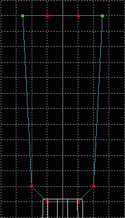
 Make sure Show Only Select Object is chosen from the etc. button on the Dialog Window, then
  Rotate the view until you see the bottom of the extruded model. Use the
  Hand Select Curve tool to select the center curve and click the
  Delete Select Curve tool to remove this curve and surface. Save current progress. guitut07.hmp
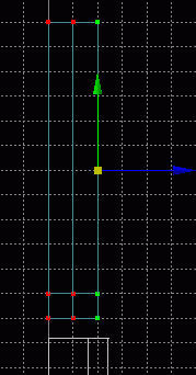
The reason we created a new patch_obj but did not rename it is that the object we just built belongs in the guitar_neck layer, but the contents of that layer would have interfered with proper modeling. So now the head needs to be placed into the proper layer. Show All Objects again via the etc. button on the Dialog Window, Select - All and click the  Cut tool from the Main tab or choose Edit - Cut from the menu. In the Dialog Window, choose the guitar_neck patch and then click the
  Paste tool from the Main tab or choose Edit - Paste from the menu. The pasted points should still be selected. In a Front view, Translate them two grid spaces (.25 grid spacing) along the Y-axis and Select - None.
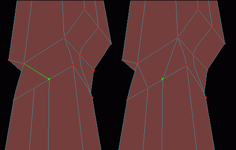
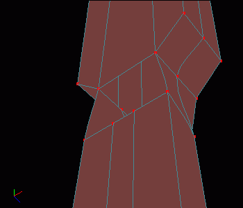 Switch to a Perspective view and Zoom in so that you can see the bottom of the head and the top of the neck. Connect corresponding points with Show - Point and - Curve on and - Surface off (using the Peak tool as necessary). However, two of the points on the neck do not have corresponding points on the head, so these must be dealt with differently.
There are 6 points in this hole and we always want to try for a 4 point patch before we settle for three point patches. Do you see where 2 four point patches can be made in place of 2 three point patches and 1 four point patch? Three point patches would probably not matter too much on this portion of the model since it will soon be made smaller, but creating only 2 patches instead of 3 is always better to do if both options will yield the same basic results.
 In a Right view,
  Square Select all points in the head. Choose Model - Rotate from the menu and type 15 in the X field. Now Translate the set of points along the Y and Z axes until the bottom leftmost point of the head is perfectly in line with the corresponding point on the neck, and lies about 1 grid space above this point. Save current progress. guitut08.hmp
Tutorial created by Jonathan Lee Dec. 31, 2001. Updated Jul. 13, 2002 for version 2.8.1.
Submit question, comments, or ask for further instruction from draven2561@hotmail.com
Part 4
Home