Home
Back to Part 2
Gear Plates
If the layers guitar_gears, guitar_pegs, and guitar_tuners are shown along with the newly modified guitar_neck layer, it would be seen that these other layers now lie in the wrong place and need to be moved, but I just realized something that is missing. There is no metal plate below the gears to prevent them from biting into the wood of the neck. I may as well add this piece now and then move the objects on top of it or else I will just have to move them again later after the plates have been built. However, the tuner assembly is too close to the edge at present to make a decent plate so it must be moved. Switch to the guitar_tuners layer and Square Select the left set of tuners and Select - Connected via the menu. UseModel - Translate to move the tuners .03 along the X-axis. Repeat the process on the right side's tuners moving them -.03. This looks better, but now the tuner head will scrape the guitar head if the tuner ever needs to be rotated. So select just the tuner heads with the Square Select tool and move the left and right sets -.03 and.03 respectively along the X-axis. Repeat for the guitar_gears layer moving the same distances left and right.
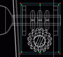 Create a new patch_obj by clicking the New button on the Dialog Window, but you do not need to rename it. In a Front view chose Model - Insert - square and use Model - Translate to move it up 12 units along the Y-axis near the head. Select the upper leftmost point and the curve extending to the right from it and choose Model - Subdivide Select Curve and type 2 in the entry field. Repeat the process on the bottom leftmost point to add an extra point at the top and bottom. With all points selected
  Scale the square in the X and Y axes separately until it is slightly wider than the total width of the two boxes and taller than the combined height of the boxes and their gear. Click the
  Extrude tool, choose Model - Translate from the menu and type .03 in the Z field. Click the Scale tool and scale the extrusion smaller until it almost aligns with the outer lines of the boxes from the guitar_tuners layer. Connect the two corresponding points on the extruded spline and peak the added curve.
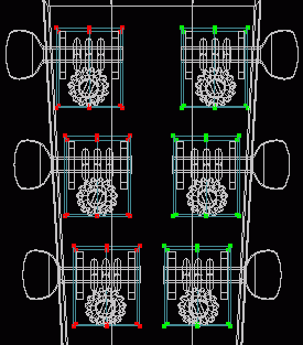 In a Right view with only guitar_neck and the current layer (patch_obj_00) showing. Use the
  Rotate tool to match the angle of the head and Translate the plate to rest on the head. Check what it looks like in a Front view. Choose to Show the guitar_tuners and guitar_gears layers as well. Switch back to that temporary patch_obj_00 layer and reposition the plate along the X-axis as necessary. You could Scale the plate larger and add screw heads, but I do not wish to at present.
  Clone the plate and position one under the two tuner assemblies below. Check in both a Front and Right view for proper alignment. Once you have three plates properly aligned Select - All and choose Model - Mirror X from the menu (this only works correctly in this instance because the model is centered at the origin).
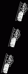
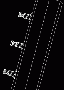
The tuner assemblies now need to be correctly placed atop the new plates. Switch to a Right view and click the Multi Obj. tab on the toolbar. Click the Translate tool and a pop-up window should open displaying the available patches to select. Select guitar_gears and guitar_tuners then move them outward to rest on top of the plates. You will probably have to Rotate them a little as well. Get out of Multi Obj. by clicking the Patch tab and the Translate tool. If anything still needs to be moved choose its layer and Translate or Rotate it as necessary (I had to rotate and translate the middle tuner assemblies independently). When the tuner assemblies are aligned show only the guitar_neck and guitar_pegs layers and repeat the Multi Obj. process to align them on the newly beveled head. When everything is aligned return to the temporary layer, Select - All points and Edit - Cut. Switch to the guitar_gears layer and Edit - Paste. Delete the temporary layer by selecting it and pressing the Delete button on the Dialog Window. Save current progress. guits04.hmp
Bracing
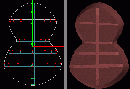
 There may be a time when the desired camera angle would provide a clear look into the hole of the guitar and all that would be seen is the flat back. A bracing needs to be inserted in a new layer so that it can be turned on and off as needed. Create a new patch_obj by clicking theNew button on the Dialog Window, rename it guitar_body_bracing and change the color to be the same as the guitar_body_back layer's and then lighten it a few shades. Show only the guitar_body_bracing and guitar_body_back layers and with a grid setting of .1 and Grid Lock - All selected, draw the outline of a cross bracing (as shown above) in a Top view. When completed
  Peak the entire spline, Extrude it in a Front view 1.5 grid spaces, and in a Perspective view Zoom in and connect the two upper corners to the center lower point to form three 4 point patches on either side. Clone the brace and translate along only the Y-axis to the waist and scale to fit along only the X-axis. Clone again and Scale it slightly larger in the Y-axis and move it down to the center of the lower bulge and scale in the X-axis to fit. Clone again and move up the Y-axis between the larger and smaller braces. Clone once more and choose Model - Rotate from the menu and type 90 in the Z field. Scale slightly in the Z-axis and in a Top view translate the brace towards the back of the guitar a little more. I may never need the bottom two cross braces, but I just thought I should make them in case I ever do.
 Tutorial created by Jonathan Lee Jan. 12, 2001. Updated Jul. 14, 2002 for version 2.8.1.
Submit question, comments, or ask for further instruction from draven2561@hotmail.com
Part 4
Home