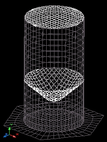
Structural Engineering CAD applications
Home | Customizing | CAD applications | Software developmentStructural projects | About the author | Contact me | Link

FORE PAGE   NEXT APPLICATION
 
automatic finite element modeling (FEM) of silos

A silo is a tall hollow tower use for storing granular goods like cement or grains.
This application generates automatically the AutoCAD geometrical model of silos. The model consists of foundation slab, walls, bottom and top formed all of them by a lot of tiny plates (finite elements) interconnected each other. 

The foundation slab can be triangular, squared or whatever regular polygon. The bottom of the silo can be flat or conical and the top is optional.

The finite element is represented by 3D FACE AutoCAD entities.

Once finished the model, it can be exported to the desired structural analysis program.

operation
By typing GENSILO at the command prompt of AutoCAD the application starts displaying the sequence showed at the right. When the user complete this sequence, the whole model will be also finished. 

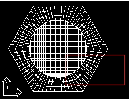
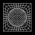
3D-FACE entities are used to model the silo which takes form by attaching perfectly thousands of those entities each other. The example at the right is made of 1896 entities. The size of these entities is base on user preference so that the density is perfectly controlled.

The application uses drawing units (as it is usual in AutoCAD), so that the user decides if they are centimeters, meters or whatever.

Command: GENSILO
Silo diameter <8.0: 8.0
Total height <15.0: 15.0
Top slab? Yes/No <Yes: yes
Number of sides for foundation slab <6: 6
Diameter foundation slab <12.0: 12.0
Finite element size <0.8: 0.8
Height of bottom from ground <6.0: 6.0
Bottom Flat/Conical <Conical: c
Cone main diameter <8.0: 8
Cone minor diameter <1.5: 1.5
Cone height <3.0: 3.0
Making cone....
Making slab....
Making walls....
Ready.

the foundation
The foundation of the silo consists of an slab shaped into a regular polygon. The user decides the number of sides of this polygon and they are not limited (of course 3 are required at least!).

The picture above at the left shows the foundation plan of a silo with an 6-side slab. The region in the red frame is showed amplified at the right.

Example of a square foundation. Three, four or whatever number of sides are posible.

top and bottom
The top and bottom of a silo are available. The user enters the bottom level and chooses from a flat or conical appearance. If the user chooses a conical bottom then the application inquires cone height, major diameter and minor diameter otherwise the flat bottom is drawn. The top is drawn only if the user requires it and always is flat.

structural analysis
When the model of the silo is finished it has to be exported to the structural analysis software. You can achieve this by means of a DXF file. Write the DXF file from AutoCAD and then read it from the structural software. Most of structural analysis software is capable of importing DXF files. The DXF (drawing exchange format) file is an industry standard wide world accepted. You can also test cut&paste technique, may be it is supported by your structural software.


        Home | Structural projects | CAD applications
         Software development | About the author | Contact me | Links

The CAD developments showed in this pages are under copyright by Abraham Mascorro
AutoCAD and AutoLISP are trade marks of Autodesk
© Copyright 2000 Abraham Mascorro. All rights reserved.