 |
|
|
|
|
|
|
|
|
|
|
|
|
|
|
|
|
|
|
|
|
|
|
|
|
|
|
|
|
|
|
|
|
|
|
|
|
|
|
|
|
|
|
|
|
|
|
|
|
|
|
|
|
|
|
|
|
|
 |
|
|
|
MPR027 - GROUP 3 - BIKE PUMP PROJECT |
|
|
|
|
|
|
|
THE PRODUCT |
|
THE PROCESS |
|
|
|
|
SCHEDULE & WBS |
|
|
|
|
|
GROUP INFO |
|
|
|
|
|
MEETINGS |
|
|
|
HOME |
|
|
|
|
|
|
|
|
|
|
|
|
GOALS |
|
|
|
|
|
|
|
|
|
|
|
|
|
|
|
|
|
 |
|
|
|
THE CNC LATHE |
|
|
|
Pinacho - Mustang 200 |
|
|
 |
|
|
|
|
|
|
This modern machine offers free and easy access to the inside of the machine by robots. The combination of the high speed of the headstock, slides, and carriges, allow us to achieve fast and accurate machining. The spacious, well thought out design enables the Motoman robot to work inside and around the lathe, making it a nice addition to our cell. |
|
|
|
|
|
Program History |
|
|
|
The first program that was written made a fully functional handle, but left the robots waiting 3 minutes for the machining of the handle to finish. So, to cut down the machining times, profileing cycles were created to combine individual cycles into one. This greatly reduced the time for machining and still produced a functional handle. Still, machining was the bottleneck of the operation, so the next step taken to reduce time was to reposition the commands so that multiple things could be done at the same time. Both the profiling cycles and order of commands will becovered when the whole program is explained below. |
|
|
|
Program Contents |
|
|
|
The program starts with a wait for signal command (M54). The lathe recieves this signal from the PLC when the Motoman has put the raw material into the lathe and has exited. The first thing that happens is the sliding door is closed (M50). Then the first profile cycle will begin. |
|
|
M54
M50
Profiling Cycle 1
M05
M51
Positioning Cycle 1
M05
M00
M50
Grooving Cycle 1
Profiling Cycle 1
Drilling Cycle 1
Profiling Cycle 1
M05
M51
Positioning Cycle 1
M05
M0 |
|
|
|
|
|
|
The first profile cycle is a combination of one facing cycle, two turning cycles, and three radius cycles to make up the outer shape of the upper part of the handle which can be seen in figure 1. When the first cycle is complete, the spindle is turned off (M05) and the door is opened (M51). The reason for turning the spindle off now is so that the spindle will have stopped rotating when the Motoman has come in to flip the handle. While the door is opening, the toolpost is |
|
|
|
|
 |
|
|
|
|
|
|
|
Figure 1: Drawn In Ideas 8 |
|
|
|
|
|
|
|
|
changing tools and repositioning itself to be ready to make the next cut. It was found that by doing these commands at the same time we could reduce the waiting time of the motoman to less than one second. The next command (M00) shuts the lathe off and stops the spindle until it receives its next signal from the PLC. |
|
|
|
|
|
After the handle is flipped, the door closes (M50), and the grooving cycle starts. This cycle cuts off the excess material needed to hold the part throughout the first machining operation. The program was written so that only 15mm of material was needed to be removed to reduce raw material costs. The next cycle is the second profiling cycle. This cycle combines a facing, a radius, and a turning cycle, and shapes the bottom larger diameter of the handle. See figure 2. |
|
 |
|
|
|
|
|
Figure 2: Drawn In Ideas 8 |
|
|
 |
|
|
|
|
|
|
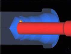
Once that is finished, the drilling cycle begins. This cycle drills a 21mm diameter hole 50mm deep pecking 10mm depths. Once the drilling is finished, the inside profile starts. This is the most complex area of the handle. The tool used in this profile is shown in figure 3. There are 11 points defined in this profile to create the finished inside of the handle seen in figure 3. After the inside profile is complete, the spindle is stopped (M05), the door is opened, and the |
|
|
|
|
Figure 3: Drawn In Ideas 8 |
|
|
|
|
|
|
toolpost changes tools and postitions itself for the new piece of raw material. The final command is the M02 command stops the lathe and returns to the beginning of the program.
Through the use of profiling cycles and setting the toolpost ready for the next operation, the machine cutting time has been cut in half. Which has made it possible to achieve a well balenced cell with the absence of bottlenecks. |
|