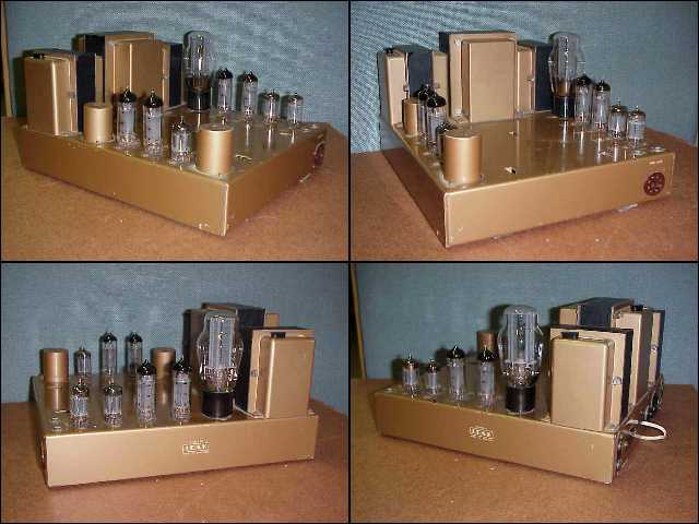
The history of this amplifier starts on 1 May 1959, remains rather blank until it was found by a friend of the owner in a factory in a very dirty state. At the time he didn't know what exactly he was given, except for the fact that it was an old valve amplifier. After he showed it to me I was soon to tell him what a gem he now posessed. Looking at the tag board there was the ominous signs of a charred component, value and type unknown.The circuit diagram was the first step and a bit of surfing produced an excellent web site, Kiewa Valley Stereo, with the diagram I was looking for and a lot more information on Leak amplifiers. The only thing missing was a list of modern replacement components.
I made a list of the components by looking at the circuit diagram and the tag board, to compare voltage ratings for capacitors and power ratings for the resistors. I then went to speak to the owner of Capetronics, an local electronics shop, to ask his expertise on this matter. He restores antique valve and audio equipment for a very impressive private museum he has. After much discussion I was able to compile a list of suitable replacement components with the correct power ratings and voltage ratings.
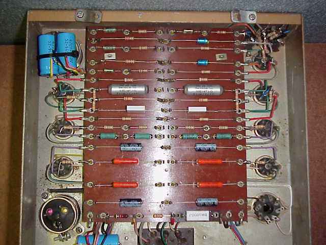
The loom wiring was corrected where it had been crushed or where the original neat 90 degree bends flattened. The missing resistor(R21) was found to be a 100 Ohm of unknown rating, so after checking the circuit diagram a wire wound 5W resistor was chosen as a safe rating. I later found out that this resistor was originally a 3W. It was deliberately chosen to be run close to it's maximum dissapation for mains transformer protection reasons. This mountings for this resistor were clipped to enable the resistor to desolder itself in the event of overheating due to circuit problems. Therefore it is not safe to over rate the replacement component. I have changed mine to a lower wattage recently.(Thx to LVRC for reminding me to add this info.)

Then the task of replacing all of the tag board components was undertaken, with extreme care. (The object was to get the amplifier looking good and above all, sounding good.) I took my time to make sure about straight leads and mounting all of the components facing the same way, except the electrolytic capacitors of course. Some components I did not replace immediately were the four 25uF, two 250nF and two 100nF non polarised metal can capacitors (All 350V rating). I did however remove them and after testing each, I found they were still OK for their storage of voltage. They were later replaced because of imperfect operation and DC isolation.
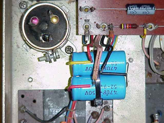
The only odd looking replacements were my components for the two dual high tension smoothing capacitors which stick through the chassis. There are replacements available of almost exactly the same size, made by LCR in England but they were very expensive. Beside that they had blue plastic covers and would not have looked the part, so an alternative was used.
The original 32u-32u-450V capacitors were left sticking out the top of the chassis and each was replaced in the circuit using two 47uF 450V caps wired together to form the same combination electrically, and cable tied to the underneath of the chassis, hidden from view. Then testing time arrived. Some old valves were chosen to be used during the first startup. Turning such an old amplifier on for the first time is a nervous moment. You never know when something might go bang ! Fortunately nothing did, and I proceeded to measure DC voltages all over the place, comparing them to the corresponding points shown on the circuit diagram. All was not well, because after checking voltages on the pin 3's of the EL84's, I decided to feel how warm the 100 Ohm resistor R21 was getting. I burnt my finger and at the same time saw that the solder holding it in was molten. I quickly measured the voltage drop accross R21 and then turned everything off. The voltage drop was 38V!!! Something was very wrong.
I proceeded to check the circuit carefully for short circuits or any strange tell tale signs but found none. It was at this point that I decided to replace the remaining capacitors and the results were immediately better. I purchased new EL84's made by Sovtek and a 5U4R rectifier valve and replaced the old good for nothing valves I was using. The same testing sequence for testing was followed and the results were really good. I measured the speaker output points for anything untoward, and decided to try the amplifier with sound.
With an apprehensive confidence I connected a speaker to the one output, and then carefully touched the corresponding input. There was the definite sound of life crackling through ! Using my electric guitar with it's very low input voltage signal source properties, I made the first sound through the amplifier and it was clean, crisp, and sounded fantastic.
I subsequently connected decent speakers to the outputs, plugged a CD player through a volume control into the inputs and listened to some music, and I was astounded. It really caught me by surprise. There was one word I could think of : Wow ! Then I listened to music for the rest of the day. The amplifier wasn't turned off for about 7 hours.
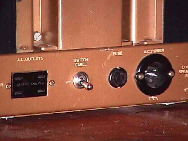
The final steps taken were to make a base for the chassis, as the original was missing in action. For this I used some 3mm hardboard (also called MDF). I decided to replace the cable switch wire with a switch in the chassis using the same location .
I marked the size of the switch around the existing hole and, using a round metal file, I carefully reamed the hole until the switch could be fitted. Then after wiring it up, I also removed the wires leading to the AC outlets. These are not needed anymore and could only pose unnecessary danger. All live and high tension connections were also insulated using heat shrink tubing. My advice to anyone lucky enough to have aquired a non working Leak, restore it, and you won't be dissapointed. If you have one in working order, well enjoy it ! Queries and comments on the web site or the amplifier are most welcome.
Colin Gray, 24 April 2000
Cape Town, South Africa