| |
Silicon Designs, Inc. | Model 2422 |
| Triaxial Analog Accelerometer Module | ||
FEATURES
|
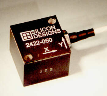 |
| DESCRIPTION The Model 2422 triaxial accelerometer module combines three orthogonally mounted Model 1210 integrated accelerometers in an anodized aluminum case for measuring accelerations in commercial/industrial environments. It is tailored for zero to medium frequency instrumentation applications. Each of the three internal accelerometers contains a miniature, hermetically sealed, micromachined capacitive sense element and a custom integrated circuit sense amplifier. It is relatively insensitive to temperature changes and gradients and its frequency response includes DC. |
|
OPERATION
The Model 2422 produces three differential analog output voltage pairs (AON
& AOP) which vary with acceleration as shown in the figure below. The outputs
can be used in differential mode or single ended, referenced to halfway between VDD
and GND. The output scale factor is ratiometric to the applied VDD voltage
and both AON & AOP, at zero acceleration, are equal to halfway between VDD
and GND. The "Z" axis is perpendicular to the bottom of the package, with
positive acceleration defined as a force pushing on the bottom of the package. The
"X" and "Y" axis directions are marked on the cover with positive
acceleration defined as acceleration in the direction of the axis arrow.
SIGNALS
|
 |
ABSOLUTE MAXIMUM RATINGS *
Case Operating Temperature ..................... -55 to
+125°C
Storage Temperature ..................................-55 to +125°C
Acceleration Over-range .........................2000g for 0.1 ms
Voltage on VDD to GND ............................-0.5V to 6.5V
Voltage on Any Pin to GND 1............-0.5V to VDD+0.5V
Power Dissipation ...............................................250 mW
* NOTICE: Stresses above those listed under "Absolute
Maximum Ratings" may cause permanent damage to the device. These are stress ratings
only. Functional operation of the device at or above these conditions is not implied.
Exposure to absolute maximum rating conditions for extended periods may affect device
reliability.
| Model Number | 2422-005 | 2422-010 | 2422-025 | 2422-050 | 2422-100 | 2422-200 | Units |
| Input Range | ± 5 | ±10 | ±25 | ±50 | ±100 | ±200 | G |
| Frequency Response (Nominal, 3dB) | 0 - 400 | 0 - 600 | 0 - 1000 | 0 -1600 | 0 - 2000 | 0 - 2500 | Hz |
| Sensitivity (Differential)2 | 800 | 400 | 160 | 80 | 40 | 20 | mV/G |
| Max. Mechanical Shock (0.1 ms) | 2000 |
G | |||||
| Parameter | Min | Typ | Max | Units |
| Cross Axis Sensitivity | 2 | 3 | % | |
| Bias Calibration Error3 | 1 | 2 4 | % of span | |
| Bias Temperature Shift (TC= -55 to 125°C)3 | 50 | 200 4 | (ppm of span)/°C | |
| Scale Factor Calibration Error 3,5 | 1 | 2 | % | |
| Scale Factor Temperature Shift (TC= -55 to 125°C)3 | +300 | ppm/°C | ||
| Output Noise (0 - 1.0 kHz) | 800 | µV (RMS) | ||
| Non-Linearity (-90% to +90% of Full Scale)3,5 | 0.5 | 1.0 4 | % of Span | |
| Power Supply Rejection Ratio | 25 | dB | ||
| Output Impedance | 90 | Ohms | ||
| Operating Voltage | 4.75 | 5.0 | 5.25 | V |
| Operating Current 3 | 18 | 25 | mA | |
| Mass (not including cable) | 21 | grams | ||
| Cable Mass | 18 | grams/met |
| Notes: |
|
ESD CONSIDERATIONS: The Model 2422 accelerometer is a CMOS device subject to damage by large electrostatic discharges. Diode protection is provided on the outputs but care should be exercised during handling of the cable wire ends. Individuals and tools should be properly grounded before coming in contact with the cable wire ends.
SPECIFICATIONS SUBJECT TO CHANGE WITHOUT NOTICE