|
|
|||
|
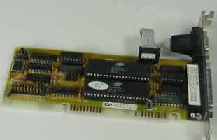
How Serial Ports Work
Considered to be one of the most basic external
connections to a computer, the serial port has been an integral
part of most computers for more than 20 years. Although many of the
newer systems have done away with the serial port completely in favor
of USB connections, most modems still use the serial port, as do some
printers, PDAs and digital cameras. Few computers have more than two
serial ports.
Essentially, serial ports provide
a standard connector and protocol to let you attach devices, such as
modems, to your computer. In this edition of you will learn about the
difference between a parallel port and a serial port, what each pin
does and what flow control is. UART Needed The name "serial" comes from
the fact that a serial port "serializes" data. That is, it takes a byte
of data and transmits the 8 bits in the byte one at a time. The advantage
is that a serial port needs only one wire to transmit the 8 bits (while
a parallel port needs 8). The disadvantage is that it takes 8 times
longer to transmit the data than it would if there were 8 wires. Serial
ports lower cable costs and make cables smaller. Before each byte of data, a
serial port sends a start bit, which is a single bit with a value of
0. After each byte of data, it sends a stop bit to signal that the byte
is complete. It may also send a parity bit. Serial ports, also called communication
(COM) ports, are bi-directional. Bi-directional communication
allows each device to receive data as well as transmit it. Serial devices
use different pins to receive and transmit data -- using the same pins
would limit communication to half-duplex, meaning that information
could only travel in one direction at a time. Using different pins allows
for full-duplex communication, in which information can travel
in both directions at once.
Serial ports rely on a special
controller chip, the Universal Asynchronous Receiver/Transmitter
(UART), to function properly. The UART chip takes the parallel output
of the computers system bus and transforms it into serial form for
transmission through the serial port. In order to function faster, most
UART chips have a built-in buffer of anywhere from 16 to 64 kilobytes.
This buffer allows the chip to cache data coming in from the system
bus while it is processing data going out to the serial port. While
most standard serial ports have a maximum transfer rate of 115 Kbps
(kilobits per second), high speed serial ports, such as Enhanced
Serial Port (ESP) and Super Enhanced Serial Port (Super ESP),
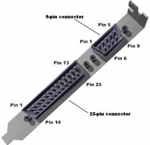
can reach data transfer rates of 460 Kbps. The Serial Connection 9-pin connector: Carrier Detect -
Determines if the modem is connected to a working phone line. Receive Data - Computer
receives information sent from the modem. Transmit Data -
Computer sends information to the modem. Data Terminal Ready
- Computer tells the modem that it is ready to talk. Signal Ground -
Pin is grounded. Data Set Ready -
Modem tells the computer that it is ready to talk. Request To Send
- Computer asks the modem if it can send information. Clear To Send -
Modem tells the computer that it can send information. Ring Indicator -
Once a call has been placed, computer acknowledges signal (sent
from modem) that a ring is detected. 25-pin connector: Not Used Transmit Data -
Computer sends information to the modem. Receive Data - Computer
receives information sent from the modem. Request To Send
- Computer asks the modem if it can send information. Clear To Send -
Modem tells the computer that it can send information. Data Set Ready -
Modem tells the computer that it is ready to talk. Signal Ground -
Pin is grounded. Received Line Signal
Detector - Determines if the modem is connected to a working
phone line. Not Used: Transmit Current
Loop Return (+) Not Used Not Used: Transmit Current
Loop Data (-) Not Used Not Used Not Used Not Used Not Used Not Used Not Used: Receive Current
Loop Data (+) Not Used Data Terminal Ready
- Computer tells the modem that it is ready to talk. Not Used Ring Indicator -
Once a call has been placed, computer acknowledges signal (sent
from modem) that a ring is detected. Not Used Not Used Not Used: Receive Current
Loop Return (-) Voltage sent over the pins
can be in one of two states, On or Off. On (binary value
"1") means that the pin is transmitting a signal between -3 and -25
volts, while Off (binary value "0") means that it is transmitting a
signal between +3 and +25 volts... Going With The Flow
Lets look at an example of
how flow control works: You have a modem that communicates at 56 Kbps.
The serial connection between your computer and your modem transmits
at 115 Kbps, which is over twice as fast. This means that the modem
is getting more data coming from the computer than it can transmit over
the phone line. Even if the modem has a 128K buffer to store data in,
it will still quickly run out of buffer space and be unable to function
properly with all that data streaming in. With flow control, the modem
can stop the flow of data from the computer before it overruns the modems
buffer. The computer is constantly sending a signal on the Request to
Send pin, and checking for a signal on the Clear to Send pin. If there
is no Clear to Send response, the computer stops sending data, waiting
for the Clear to Send before it resumes. This allows the modem to keep
the flow of data running smoothly. |
|||
|
|