Index | Ex 2-4 | Ex 2-5 | Ex 2-6


Ex 2-5 Lake Cabin

Exercise 2-5: Anotation & Dimensions

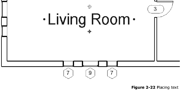
Adding text is very simply in Revit. In this exercise we will add labels to each room in our lake cabin plan. We will also place two dimensions.

Placing Text:

  1. Open Lake Cabin.rvt created in exercise 2-4.

  2. Make sure your current view is Level 1. The word Level 1 will be bold under the heading Floor Plans in your Project Browser. If Level 1 is not current, simply double-click on the Level 1 text in the Project Browser. (Figure 2-20)

  3. Select the Text tool under the Basics
  4. tab in the Design Bar.


Once again, notice the Options Bar has changed to display some text options.

The Type Selector indicates the text size. From this options bar you can also place text with arrow lines (leaders) and set the text alignment (i.e., Right justified, Centered or Left justified). We will not adjust these setting at this time. Settings are: no leader & left justified.

  1. You will now place the words Living Room. Click within the living room area to place the text. (Figure 2-22)

  2. Type Living Room, then click somewhere in the plan view to finish the text.

We notice that the text seems too large. This is a good time to explain what the text height is referring to in the Type Selector.

The text height, in the Type Selector, refers to the size of the text on a printed piece of paper. For example, if you print your plan you should be able to place a ruler on the text and read ¼” when the text is set to ¼” in the Type Selector.

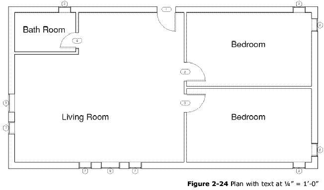
This can be a complicated process in other CAD programs; Revit makes it very simple. All you need to do is change the view scale for Level 1 and Revit automatically adjusts the text and annotation the match that scale. Currently our view scale is set to 1/8” = 1’-0”; we want the view scale to be 1/4” = 1’-0”. With the view scale set to 1/8” 1’-0” our text is twice as big as it should be. Next you will change the view scale for Level 1.


  1. In the Project Browser, right-click on Level 1 under Floor Plans. Select Properties from the pop-up menu.
  2. In the Element Properties dialog, select the Value field for the View Scale Parameter. (Figure 2-23)

  3. Click the down arrow that appeared next to the current scale (the current scale should be 1/8” = 1’-0”); now select 1/4” = 1’-0”.

  4. Click OK.

You should now notice that your text and even your door and window symbols are half the size the used to be. (Figure 2 -24)

  1. Finally, using the Text tool, place a room name label in each room as shown in Figure 2-1 and Figure 2-24 below.

  2. Save your project.


Place Dimensions:
To finish this exercise we will place two overall dimensions in our plan.

  1. Select the Dimension tool under the Basics tab in the Design Bar.

  2. In the Options Bar, change the drop-down list that says Prefer wall centerlines to Prefer wall faces. This option will allow you to dimension to the outside face of your building, as you would normally do when dimensioning the overall footprint of your building.

  3. Place a dimension by selected two walls and then clicking a third point to specify where the dimension line should be relative to the walls. (Figure 2-25)

  4. Place one more dimension indicating the depth of the building.(Figure 2-1)

  5. Save your project.

Index | Ex 2-4 | Ex 2-25| Ex 2-6