 The Comfortable Pocket Yacht
|
|
|
Trailer Sailing |
Topics Various Photographs and Drawings
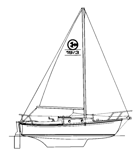
A line art drawing of the Com-Pac 19 from the manufacturer's literature
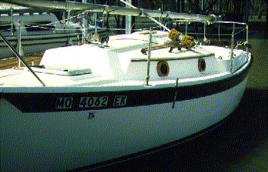
"Solar Wind" at it's slip on the Mississippi. Click on the image to see an enlarged version.
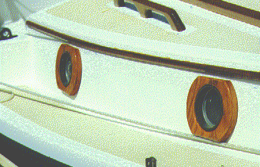
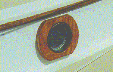
Before and after pictures of the wood trim added around the exterior of the Portholes. Each trim piece consists of a section of wood 6 inches high, 7.25 inches wide, and 0.75 inches thick. Each rectangular trim piece was rounded to a circular shape with a diameter of 7.25 inches at the ends and had a circle of 4 5/16 inch diameter cut in the middle. A router was used to give a smooth curve to the inner and outer edges. A total of six 1/4 inch deep holes were routed into the rear face to create a depression for the bolt holes. Each piece was bedded to the cabin sides with Silicone Cement. Click on the images to see an enlarged version.
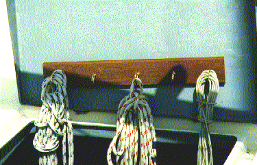
The underside of the Lazarettes where a piece of wood has been epoxied in place to hold lines and fenders when not in use. Various brass screw eyes have been installed to hold the unused lines and fenders so that they dry rapidly and do not tangle. When the lazarette is open, the lines hang toward the rear, when closed, they hang free straight down. Click on the image to see an enlarged version.
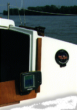
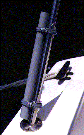
The waterproof depth finder (Humminbird Wide 100) is installed on a removable hatchboard. The board was cut from 1/2 inch veneer plywood and coated with 3 coats of Cetol marine and two coats of Cetol Gloss. More information about why I selected this model and how it is attached to the hull is in the "First Steps" section. Click on the image to see an enlarged version.
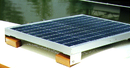
The solar panel is installed on top of the companionway hatch. The method of installation allows for easy removal of the panel when trailering or when events on deck require more freedom. While this does reduce the electrical output somewhat due to shadows from the sail and boom, I felt it was preferable to mounting on the stern rail where a large solar panel might interfere with the motor, tiller, or boarding ladder. If this does not work out well in practice, I can always change it later. Four Cetol treated blocks were bedded to the companionway hatch cover with silicone and fastened from the underside with stainlesss steel screws and backing washers. The solar panel was attached at the corners to the horizontal surface of four pieces of 2 X 2 inch aluminum angle using stainless steel bolts. The panel was then fastened to the ends of the wood blocks through the vertical surface of the aluminum angle by means of stainless steel T-Bolts and 1/4 inch stainless steel screws with lock washers. The electrical connection is by means of a short cable that passes from the sealed junction box of the solar panel to a waterproof connector on the after most part of the companionway hatch. Under the companionway hatch, a coiled cable carries the current to avoid any interference with the free movement of the hatchway. The Kyocera 40 watt panel is 20 3/4 by 25 3/4 inches and represents just about the largest commercially available panel I found that can be still be mounted on the sliding hatch cover. Click on the image to see an enlarged version.
The tiller tamer is a slight modification from the Handbook of Trailer Sailing - Second Edition. Materials:
Loop the shock cord around the starboard stern cleat and attach the hooks to the eye of one of the bowline knots. Place the other bowline eye around the port stern cleat. This results one doubled length of shock cord to starboard and a length of 3/8 nylon double braid line stretched tightly to the port stern cleat. When you want to engage the tiller tamer, just pull the nylon line forward and insert into the jam cleat. The tiller will now hold in this position with some give due to the tension supplied by the shock cord. Releasing the tiller tamer is easy - just pull the nylon line forward and then let it snap back to its normal position at the rear of the cockpit where it is completely out of the way. I'm still experimenting with this rig since the control in the funny currents of the Mississippi will be important for me. The tension supplied by the the doubled length of shock cord will need some fine tuning by changing the length of nylon line to the other stern cleat. My first attempts with three strand nylon for this line did not work well due to slippage in the jam cleat. A second attempt with two lengths of shock cord was too stiff for normal use.
The sun shade is composed of two large arches assembled from 7 sections of fiberglass tent poles. The arches are covered with a heavy duty nylon flag fabric and the stern arch is tied to the aft rail with dacron cord while the forward arch is tied to the mast with dacron cord and a 20 inch section of shock. Materials: I used a total of four sections of 3/4 inch electrical PVC plastic pipe (1 foot each) clamped to the outside on the mid-ship life lines stanchions and the stern pulpit support (the ones angled aft). These pipe sections required some vinyl tubing as spacers and will act as sockets for the fiberglass tent poles (available at Wal-Mart or any camping supply store). I used 3/4 inch material so that the sockets could also be used to support a rigid structure composed of 3/4 inch aluminum tubing at a later date. The tent poles are shock corded together and assembled into an arch. The aft arch is threaded through a pocket in the nylon cover and the forward arch is threaded through a pocket on the starboard side and closed with velcro on the port side. This allows for a slit (closed with velcro) in the forward half of the cover to accommodate the backstay and the topping lift. The shade has four tabs of nylon web material sewn into the corners. These serve to tie the shade down to the lifelines. Four other tabs are sewn about 2/3 of the way up each side and these serve as tie points fore and aft. The forward cords are attached first with the shock cord around the mast. The aft cords are then tied off to create a slight tension to the entire rig. The lower tie points at the four corners to the lifelines would only be needed in stronger winds. The entire device can be assembled in about 10 minutes.
This page was last updated: 01/19/01 08:37:25 AM |
|
Copyright © 1998-2000 Jobst Vandrey |