 |
| DTBR's Airplane Project More Wing Photos ( Holding Fixture and Finishing Tasks) |
|
 |
|
| Last Updated:11/11/01 |
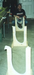
| Once the nose skin was riveted in place, the wing was ready to move to holding fixtures that provide access to both the uppper and lower surfaces. We fabricated three such fixtures for each wing, since they will also serve as storage cradles in the future. We used foam packing sheets as the padding |
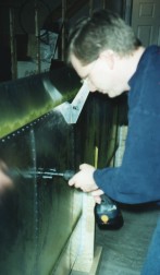
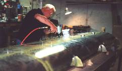
| We found the majority of the remaining tasks worked very well with the wing in these holding stands. Installation of the trailing edge skins was the first of these tasks. In this photo, I'm drilling access holes in the lower skins for the fuel drain valves. I used a fly-cutter in a variable speed drill. The drill was clutched down so that it would slip if the cutter hung-up. This worked very well for cutting large holes in the fuel tanks and in the skins. |
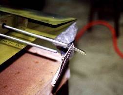
| Two steps omitted from the current wing manual, but discussed in various lessons learned is installation of the jury strut brackets and the wing tie down ring. These tasks were easily completed in the wing stands with the upper skins removed to enable access to the internal structurs. In this photo, the forward and aft jury strut brackets are show mounted along rib 2. The forward bracket is centered on the main spar cap whereas the aft bracket begins at the rear spar cap and extends forward. |
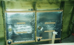
| The fuel system installation is also best accomplished while in the holding stands. Here a portion of the holding stand is blocking part of the right-most fuel tank. I later trimmed this portion of each stand in order to have better access to the wing bays. |
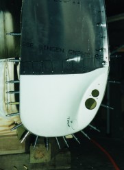
| The wing-tips on the CH-801 are a combination of aluminum and fiberglass that form a high-lift Horner tip. This feature is part of the STOL package of this aircraft. As shown, fasteners are positioned around the entire surface of the tip such that this step also worked well in the stands. However, working with the stands on the floor required that we "jack-up" the end with the wing tip in order to accomplish this task. On the Left Wing, I moved the stands and wing to the work table. This provided even better access for all the finishing steps discussed here. |
 |
 |
 |
 |
 |
 |
 |
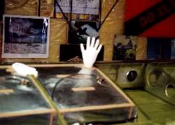
| Before closing up the wing, we conducted a leak test on the fuel system. We did this by using a piece of plastic tubing over the fuel lines along with a rubber glove over the fuel filler neck. The glove was tie-wrapped to the neck and the plastic tube clamped off after filling the system with enough air to inflate the glove. We checked for leaks with soapy water and found none. We also watched to see how long the glove would stay inflated. This is certainly not a high fidelity test, but probably good enough to find any obvious leaks. |
 |
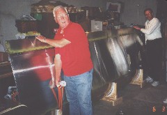 |
| Our Tech Counselor stopped by on 1 June 2001 to check out the right wing prior to closing it. He recommended adding P-Clamps to some our fuel sender wiring along with adding a couple of rivets along a doubler plate where edge distances were marginal for the current rivets. We accomplished those items and completed the right wing on 3 June 2001. The upper skin was riveted in place and we stored the wing on the holding cradles. |
| With the right wing resting safely in the back of the basement, it was time to clean the shop and get started on the left wing. The right wing took just under 5 months and a total of almost 164 hours. |