NOTE: This section covers a thorough analysis of a difficult mounting problem by graphical means (CAD), in lieu of physical trial and error. The first part examines coupler possibilities, while the second covers diaphragms. The third covers the final analysis of possible use of Walthers diaphragms and the resultant spacing. As an addendum a examinations of the possibilities on a 30" and 22" radii are is included. Although the methods are quite involved, digesting the results can explain the selection process.
COUPLERS
Bachmann cars have a pivoting draft gear box that can not be relocated easily. Before chopping up mount and drilling holes that may not be filled easily, it would be wise to measure pertinent parameters and make simple, scale drawings of possible closer coupling solutions.
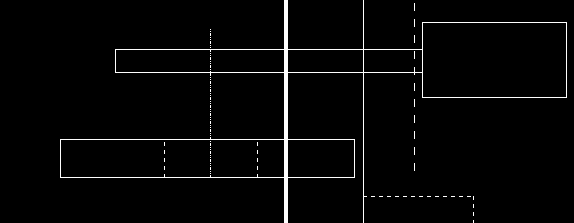
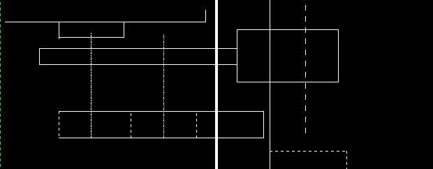
USING A CAD PROGRAM (XCAD) makes things simpler. Plotting accurate dimensions can reveal potential problems and output required measurement information. Better still data can be stored for future reference. Since this is the normal working view, the drawing is bottom side up.
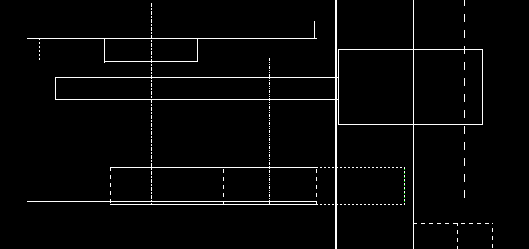
The heavy reference line represents the car end corners and for comparison the dashed prototype pulling face is at a distance of 15" = .1772".>The solid vertical, end sill line is .104" = 9.1" from the end corner line. The front edge of the box is .012" to the left of the end sill and the distance from the center post front is .130" from the front box edge. The post = .125" OD or radius = .0625", so the extended, dashed mounting center/pivot is .1925". This gives .2045" from reference line. The heavier dashed mounting post is shown for reference. To the lower right, the included diaphragm is dashed in, extended .148" = 12.9 from end sill. It should be noted, that this is past the prototype pulling face line by .080" = 7" and thus can not be used at prototype coupling distance.
The upper part of drawings are different for each coupler and mounting situation. Data is derived from MEASURING COUPLERS . The upper right rectangle represents the knuckle with horn at left and important pulling face at right. Dashed mounting center is added to shank.
Note: Adjust brightness and contrast for optimum viewing.
KADEE 5 WITH 65.7" SPACING

Note: Adjust brightness and contrast for optimum viewing.
KADEE 23 WITH 60.2" SPACING

Note: Adjust brightness and contrast for optimum viewing.
KADEE 23 WITH 30" SPACING
Note: Adjust brightness and contrast for optimum viewing.
KADEE 23 WITH 40.9" SPACING

Note: Adjust brightness and contrast for optimum viewing.
ACCUMATE PROTO WITH CORRECT PROTOTYPE 30" SPACING
The end doors will be lost with the necessary removal of the diaphragms. There is about .068" space for diaphragms, which is impractical.
ADDING DIAPHRAGMS
To determine diaphragm fit on curves, a drawing is made with the measured truck centers on the desired radius. Fist measure the the distances from end sill to truck center, between truck centers and from end sill to end corner reference.
From coupler data drawings and car measurements, the end sill and end corner reference construction can be added.

Note: Adjust brightness and contrast for optimum viewing.
ACCUMATE 30" SPACING
From the drawing, it is evident that the 30" spacing can not be used with a 36" radius. Since there is only about .023" clearance at the pushing ends the slack of .012 would just clear. However no diaphragm will fit without problems.
TRYING DIAPHRAGMS
The American Limited, Bachmann conversion uses Kadee 23, which from above, yields a spacing of 64" or 2.133 times the prototype.
Note: Adjust brightness and contrast for optimum viewing.
AMERICAN LIMITED HEAVYWEIGHT
The closest coupling would be with the standard heavy weight version which are about .134" compressed and .32 width from the car centerline at the face plate. Allowing a few thousandths, on a 36" radius, the minimum permissible pulling face to end corners would be .3305" = 27.8" for a spacing of 57.6". This is almost twice the desired spacing.
OPTIMUM CLOSE COUPLING
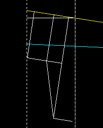
Trimmed down to two exposed bellows, the Walthers diaphragms measure about .060" compressed. From car center line, the diaphragm width is .25" and the end plate width is .325". The plate will pivot at the diaphragm end, so the narrower width is used.
Starting with the above drawing, everything was deleted but the pulling face, car center and track lines. Draw a line parallel to the car centerline at the .25" width. Draw a face plate line perpendicular to it from the pulling face intersection to the center line. Then draw an end sill line parallel to it at .060. Adjust the car center line as above, using the end sill as reference. Redraw the face plate and end sill lines. Repeat until correct.
Next draw in the end details for perspective. Then select couplers for trial and draw their mounting center lines parallel to the pulling face line at the distances found in Measuring Couplers. The small dashes are for Accumate and the larger are for Kadee 23. Measuring their respective end sill to mounting center distances at the intersections along the center line. The values would be: Accumate = .257 and Kadee 23 = .352.
Note: Adjust brightness and contrast for optimum viewing.
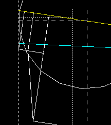
MINIMUM SPACING WITH DIAPHRAGMS ON 36" RADIUS
Examining the previous drawings, the end sill to box mounting center is .1925". The Accumate would be .0.054" away. The box screw hole is about .072" OD or .036 radius. The hole would require plugging, while the 23 appears to be at a safe distance. Load the 23 drawing with the Kadee box lid above and move the coupler section to the new mounting center.
Note: Adjust brightness and contrast for optimum viewing.
KADEE 23 COUPLERS FOR MINIMUM SPACING 36" RADIUS
The lid extends past the box rear, indicating the centering spring will not be supported by it. The spring rear (dashed line) is about .150 from the mounting center. A trial Installation of a 23 shows considerable play and sag. The internal box height equals .069", while the shank thickness with spring is .054; leaving about .015 clearance for a .388" long strip of Evergreen to be added to support the spring rear.
Since the the box front edge is set back .012" from the end sill, The box front edge mounting center is marked at .352 - .012 = .340". Then the box must be trimmed back about .030" to clear horn. The center post and box rear are removed. The box is about .248" wide, both lid and 1/4" wide strip must be narrowed for snug fit. The box is drilled and taped for a 2-56 screw, while strip is drilled 1/8" at .222 from the front end. Be sure to remove all burrs, that may interfere with operation.
Mount with shim on bottom and test for free movement. If too tight , sand shim thinner, a few thousandths. Finally cement shim to box bottom and remount coupler.
At the lower right, the dashed diaphragms show the compressed and extended relationships to the pulling face.
MINIMUM SPACING WITH DIAPHRAGMS ON 30" RADIUS

Note: Adjust brightness and contrast for optimum viewing.
MINIMUM SPACING WITH DIAPHRAGMS ON 30" RADIUS
Pulling face to end corner = .2014 = 17.55" for 35.41 spacing. End sill to mounting center =.348. Subtracting the .012" end sill to box front, the distance from the front to mounting center would be .336" or only .004" shorter than the 36" radius value.
MINIMUM SPACING WITH DIAPHRAGMS ON 22" RADIUS

Note: Adjust brightness and contrast for optimum viewing.
MINIMUM SPACING WITH DIAPHRAGMS ON 22" RADIUS
Although this radius is not recommended for 80' cars, the evaluation is included for sake of comparison, since it may yield clues for shorter cars. Pulling face to end corner = .213" = 18.83" FOR 37.66" spacing. End sill to mounting center =.336. Subtracting the .012" end sill to box front, the distance from the front to mounting center would be .324" or only .016" shorter than the 36" radius value. This should leave about a .022" wall between box and new mounting holes.
The hole in the Kadee box lid is.091" OD and the nominal #2 OD is .086" about .005" = .436" leaving for adjustment. Mounting with a #1 screw with .073" OD will leave about .018" = 1.57". A washer can be used under head, if too small.
Although the minimum spacings are not as close as the prototype, they are a drastic improvement over other recommendations. If mixing these cars with other makes, before selecting any standard spacing, it would be wise to evaluate them also. Their requirements may dictate a larger separation.
BACK TO CLOSE COUPLING, 20th CENTURY
BACK TO COUPLER EXAMPLE INDEX
