Since many early cars were basically flat cars with appended sides, ends, tanks or hopper doors, some of these cars can be modified very easily to provide a wide variety of rolling stock for the 1850' through the early 70's. They probably used chain link and hook originally, then were converted to link and pin, but were possibly converted to knuckle couplers later. For automatic coupling Kadee 711 will be used. Lacking extended striking plates, they are best judged at end sills. The frame is zamac with cast-on coupler boxes.
Mounting 711's, requires milling the box to raise pad to mount box at correct height of 29/64" This can be done by mounting a rotary tool in a drill press accessory using a small bit. The final thickness at the box floor will be about .059". A gauge can be laminated to set cutter height.
Probably the easiest way to locate the mounting center hole is to use the original. Since it is blind, a #49 drill bit can be used to mark a center dimple to drill clean through #56 tap drill for a #0 screw. The screw will be trimmed flush, after mounting. The coupler head is recessed to about the trip pin.
USING CAD DRAWINGS a thorough evaluation is made.
After milling, the car must be measured. The end sill to mounting hole front is .159" and the OD = .074" for frame edge to mounting center = .196". The box is .458" long. The endsill to frame edge = .051"
Found from Measuring Couplers, the 711 pulling face to stud rear = .406". The mounting hole = .107" The pulling face to mounting center with this box is .406 - .057 = .483". For coupler relationships see KADEE 711 EVALUATION.
The heavy line is the end sill reference and the solid line to the left is the frame edge.
Based on prototype data, at the bottom dashed in is endsill to the left and the far right dashed line is the link mid-point at 8 3/4" from the endsill for 17 1/2" separation.
The lower yellow dashed lines represent the screw at .059" OD with the original screw hole at .074" OD just outside, While the blue dashed lines are the box mounting hole at .062" OD. The yellow lines inside the shank are its mounting hole. Note that this is the center position with no pull, where spring presses shank against post.
Note: Adjust brightness and contrast for optimum viewing.
NO PULL WITH 17.2" SPACING
The PF-ES = .09875 = 8.602" for ES-ES = 17.204". By shear luck the pulling face is within .002" of the prototype.
In the maximum pulling position, the spring will compress. In this case the rear of the shank hole will be against the post.
Note: Adjust brightness and contrast for optimum viewing.
MAXIMUM PULL WITH 19.73" SPACING
PF-ES = .11325" = 9.865" for 19.73" ES-ES.
During pushing, the knuckle slack reduces distance greatly.

Note: Adjust brightness and contrast for optimum viewing.
PUSH WITH 12.89" SPACING
PF-ES = .074" = 6.446" for 12.892" ES-ES.
MINIMUM RADIUS CHECK
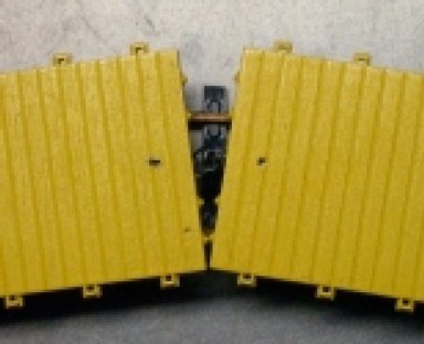
With their short wheel bases, these cars can navigate a 15" R very well. But with close coupling some problems arise during pushing, where the endsill corners or truss rod nuts touch.
Note: Adjust brightness and contrast for optimum viewing.
PUSH ON 15" R
The lower left shows the overlap.
Note: Adjust brightness and contrast for optimum viewing.
PUSH ON 15" R
During tests this did not derail cars, but it is not prototypical and could wear off paint. Fortunately the springs relieve the stress.
The problem can be corrected by adding the missing dead blocks (man killer's). Although in 1882, the MCB set a standard of an 8" square face and 6" thickness, with inside spaced 7" from center line, earlier dimensions varied drastically.
To assure function in model, an Evergreen .08" x .10" = 6.97 x 8.71" stip, cut to endsill height, is used. The verical dashed line is at the block contact point. The left car is on a tangent, while the right is on a 15" R curve.

Note: Adjust brightness and contrast for optimum viewing.
DEAD BLOCKS ON 15" RADIUS
The ensill corner clears by .0116" or .0232" fo two cars. The blocks overlap by .0085", which should prevent hang-up.

Note: Adjust brightness and contrast for optimum viewing.
PUSH ON 15" R
Coupling actions are not possible on curves and are limited to tangents or very large radii. The spring action will duplicate the prototype movements that must have been present with hook and chain.
BACK TO COUPLER EXAMPLE INDEX
BACK TO KADEE 711
BACK TO 19TH CENTURY
