These cars come with talgo mounts and long cast-on diaphragms that may interfere with close coupling. Although they will run on an 18" radius, 30" or greater is recommended for appearance. Since the ends have a .015" = 1.3" raised rim around the edges, spacing measurements must account for it. The diaphragm extends .151" from the end sheet so the end corner is .0136" back. Using an article recommendation of 3/8" mounting center set from the end reveals the following.
NOTE: During height adjustment, The same article recommends using 1/8" OD tubing for truck kingpin, while the truck hole is .142" OD. This creates .142 -.125 = .017" play. This could produce almost 1.5" offset, if the car were fully skewed in opposite directions and ends. It might be better to use the push pin which is .136" OD for .006" play or a #3 screw at a nominal .138".
USING A CAD PROGRAM (XCAD) makes things simpler. Plotting accurate dimensions can reveal potential problems and output required measurement information. Better still data can be stored for future reference.
A recent article claims that mounting center from car end should be 3/8" for heavy weights and reduced to 5/16" for light weights to prevent corner collisions, which yields close to prototype spacing. This drawing shows end relationships.

Note: Adjust brightness and contrast for optimum viewing.
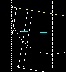
#5 WITH 3/8" END TO MOUNTING CENTER ON 36" R
The small circle was used to position car on track, while the larger was used for measurement.
The pulling face to end corner reference = .238 = 20.73" for a spacing = 41.46. This is about 10 1/2" greater than and 1.38 times the prototype spacing of 30". The drawing shows, the statement appears to be incorrect. It definitely shows that one size does not fit all.
PROTOTYPE SPACING
Since this is the normal working view and only horizontal measurements are required, the drawing is bottom side up and vertical dimensions need not be to scale. The dashed prototype pulling face is drawn 15" = .1772" from the heavy reference line at the car end corners for comparison.
Next from the constant car measurements, the drawing was plotted. A raised ridge = .015" runs around the edge. The end sheet line is shown to the left of the reference line to represent this. A second line to the left shows the wall thickness = .056". The heavy dashed, cast-on diaphragm is in the lower right, with end at .151" from end sheet.
In the upper part, the #5 is drawn from data found in MEASURING COUPLERS . The upper right rectangle represents the knuckle with horn at left and important pulling face at right. Dashed mounting center is added to shank with box lid, for reference.

Note: Adjust brightness and contrast for optimum viewing.
PROTOTYPE SPACING WITH #5 and ALH DIAPHRAGM
Since it is easier to measure mounting center from rear of wall and it will be permanent, after any modifications, this will be used. The wall rear to mounting center = .234".
Examining for diaphragm fit, The pulling face to end sheet = .187". The cast-on diaphragm is .036" from the pulling face, permitting no diaphragm to fit. With compressed length of .136" and extended of .219", the American Limited Heavyweight appears to fit well and is lightly dashed in to view relationships. The cast-on diaphragm should be removed, flush with the end sheet.
To check effects on a 36" curve, a drawing was made.
Note: Adjust brightness and contrast for optimum viewing.
PROTOTYPE SPACING WITH ALH DIAPHRAGM on 36" R
The pulling face to end corner clearance = .063", which should not cause any problems. However the pulling face to diaphragm end plate, tilt point, clearance is only .0114", which is close. A wider separation may be suggested, especially on sharper radii.
OPTIMUM COUPLING
Using the Bachmann Spectrum pulling face to end corner = .1969 = 17.15" for 34.3 spacing, the following is drawn.

Note: Adjust brightness and contrast for optimum viewing.
OPTIMUM SPACING WITH ALH DIAPHRAGM on 36" R
The wall rear to mounting center = .210". The pulling face to end corner clearance = .101", which should not cause any problems. The pulling face to diaphragm end plate, tilt point, clearance is .0.36", which should be sufficient.
BACK TO COUPLER EXAMPLE INDEX
BACK TO 20TH CENTURY
