Torque is a measurement of twisting ability about an axis. Basically it is a force vector (F) applied at a distance (R) which is measured in ounce-inches, pound-feet, dyne-centimeters, newton-meters or gram (force)-centimeters. For the relationships of these units, go to SHORT DISCUSSION IN PHYSICS
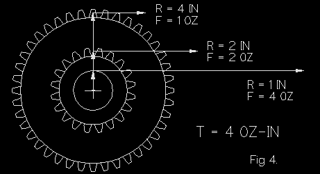
The above shows that torque is constant for all gears or drivers fixed to a shaft. Not shown for clarity, a driver would appear as a larger wheel on the same shaft with the same torque but less force.
A good example is a torque wrench, which measures torque at the thread radius of a screw or nut by applying a force at the bar end.
GEAR TRANSFER FUNCTIONS

Examination should reveal the transfer functions. The (right) driving gear with 20 teeth, 1 inch radius and 2 ounce-inches torque rotates CCW at 200 RPM and and exerts a 2 ounce force on the driven gear with forty teeth for a ratio of 2:1. Ratios are usually stated as driven teeth:driver teeth.
NOTE: The following relationships are totally independent of the gear pitch. They also hold true for pulleys using diameter or radius ratio. No slippage is assumed. The direction of rotation is not reversed.
If the teeth are of equal size to permit proper mesh, the driven gear must have 2 inch radius. During one revolution of the driver, 20 teeth pass 20 teeth on the driven, resulting in only one half revolution CW, which means the driver must turn twice for the driven to turn once. This produces 100 RPM or a 2:1 speed reduction.
Often misunderstood, torque transfer is not quite so obvious. Since the driver output force is at a radius of 1 inch:
This same force is applied to the the driven at a radius of 2 inches:
The torque ratio is 2:1 increase.
The converse holds true, if the left gear is the driver for a ratio of 1:2.
Note: ¶ = pi = 3.14159
Since POWER = (2 * ¶ * k) * torque * RPM
BASIC RULES
RPM is divided by the gear ratio.
TORQUE is multiplied by the gear ratio.
POWER does not change during the transfer.
IDLER AND COMPOUND GEARS can be treated as two gears, using the total gear ratio.
This can be found by measuring deadhead current at 12 v. using the info under MOTOR GRAPHS.
MULTIPLE GEAR FUNCTIONS
Idlers are used to adjust input to output shaft spacing, to power parallel shafts and to reverse direction. Many examples exist in N Scale and Athearn's gear boxes are good examples of multiple sizes in one train. The number of idlers does not effect overall gear functions.
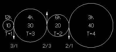
Using the left gear as the input with 10 teeth, T = 1 oz-in and RPM = 12 K CW, the second gear is driven at a 3:1 ratio yielding the results shown but rotates CCW. Each pair follows the same rules. An odd number of idlers preserves the rotation direction, While an even number reverses it.
The important thing to note is the relationship between the input and output gears. If there were no idlers between them the ratio would be 4:1 and yield identical results. The product of the ratios yields:
COMPOUND (STEP) GEARS
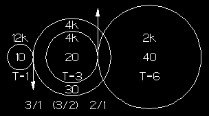
Here the two center gears are fixed on the same shaft resulting in a step or double reduction gear. The relationship of the first two gears does not change, but since the second and third gear are fixed on the same shaft, their torque and RPM are the same. These are transferred from the third to the output gear by their ratio. Total ratio is again the product of the ratios.
Since in most regear projects, the input is often a worm or the smallest pinion available and output gear is limited by driver size, these are selected first. Dividing their ratio into the total desired yields the step gear ratio. (Shown in parentheses)
The step gears can be any combination that yields the ratio:
Selection is by fit.
Required motor torque = 2.755 / 31 = .089 oz-in = 6.399 gmf-cm.
A Mantua/Tyco Pacific pulls about 3.5 oz with 80" drivers and a 26 / 1 gear ratio.
But, friction, at gear faces and in bearings, exerts forces at radii and RPM, thus this develops torques and power which the motor must supply additionally. These are usually minor, when compaired to the torque gain of the gear ratio. This can be determined from a motor graph by plotting the deadhead speed point on the RPM line. The torque value is that required to move the loco alone. The actual torque required is the sum of both. It can be seen that higher gear ratios reduce required motor torque at higher motor RPM.
Since, except for friction losses, power remains constant across a gear train, calculating power at the drivers is sufficient. Assuming a 3 oz drawbar pull at 80 SMPH with 80" drivers on a level track.
T = 80 / 2 * .01148 * 3 = 1.3776 oz-in = 99.1872 gmf-cm.
N = speed (S) / Driver diameter (D) * k
From the EQUATIONS DERIVATION , where is the universal axle speed constant, the latter reduces to:
P = 99.1872 * .336 * .00256725 = .08557 watt
Going up a grade the drawbarpull may double for .171 watt. It would appear that most motors would handle this.
BACK TO MOTOR GRAPH
BACK TO ANALYSIS
BACK TO REMOTORING
BACK TO REGEARING
BACK TO REPOWER DON'T KNOW WHY
BACK TO STARTING TRACTIVE EFFORT
BACK TO SUPER MOTOR
