What is a super motor? Ask and you will receive a wide variety of answers, many of which will be conflicting. It should have low current draw and noise, high torque and power, correct speed match to gear train, good fit and size, easy maintenance and probably many others. At present none can meet all requirements or even approach them. Ask an "expert" and he will claim A is better than B because...... Then ask for the facts to prove this. The only true fact is that there is very little data for comparison to support any claim. Since our market is very small, we can not expect a wide selection of motors specifically designed for our purposes. You take what you can get. Choice is determined by your needs and should not be based on hearsay, but on the best data available.
Motors are not isolated entities, but integral parts of a power train. Thus an overall understanding of REPOWERING is required for better selection. Too often hype suggests replacing old motors with brand X can motors without any corroboration. How do they actually compare? Can an old motor be salvaged or improved to avoid hacking a prize collector's item? You can find some factors to help judge, below.
From the basic motor equations, there are only two relatively easy ways to improve an existing motor in order to reduce speed or increase torque. These are to increase the number of windings or the flux. These are not practical with can or other enclosed motors. In many even replacing brushes is a monumental task.
Although, when the slot car rage was in, many motors were rewound (or more likely unwound to remove turns) to increase speed, the process is very tedious requiring special winders for ease. Until more recently increasing flux with stronger magnets was not feasible.
Examine the basic equations for motors to determine what might be changed. The use of the term flux is generic to avoid confusion and simplify.
For RPM, voltage and poles can not be changed, while increasing magnet flux or number of armature turns will decrease RPM.
For TORQUE, again poles can not be changed, while increasing flux or turns increases torque. Current is not an independent variable, but depends on the total resistance of the wire at any given voltage. The resistance of the wire decreases with size increase and increases with length. Increasing resistance will decrease current and torque. This produces a paradox in rewinding, since increasing turns will almost always increase resistance, due to space limitations.
Since power is based on the product of the first 2 equations, a surprising result occurs.
This reduces to:
Power will be in mouse power: MP = .001 HP = .75 W.
But the voltage is the net, actually applied to the armature. That is the applied voltage at the brushes minus the counter voltage generated by the rotation of the armature .
Since efficiency reduces to: EFF = C * V * I * N * F / F / N / V / I = C, apparently changing these does not effect it. But increasing flux and thus torque will lower no load current , changing the slope of the line. This will increase efficiency. The constant C contains many factors that could change through any alteration of the variable parameters. The magnetic field interactions between armature and pole pieces is very complex. The changing fields cause hysteresis effects in the ferro-magnetic materials, which effect losses. Increasing the magnet fields increases loop areas and enough could cause saturation. Much of the effect is determined by physical geometry and material selection.
This apparently indicates that voltage and current are the only factors in power. Many texts simply state: output power = (supplied voltage minus counter voltage) * current. But neither factor is independent of the other parameters. Counter voltage increases with RPM and turns. There are other factors hidden in the quasi constant k, which are variable at different loads and may effect any changes made.
The easiest way to examine change results is to draw GRAPHS of the old and new and compare. Power and efficiency curves need not be drawn. Values can be calculated easily at points of interest. As a reminder, these graphs are idealized approximations, showing relationships rather than actual accurate values. The RPM line for real motors is very rarely straight.
Note: Adjust brightness and contrast for optimum viewing.
Original motor graph.
With the maximum continuous current of 1.1 amp, usable operating values are 8 K - 5 K RPM, 1.2 oz-in torque and 6 MP. Note that this is less than the maximum power torque point and great than the maximum efficiency point.
Assume it is possible to squeeze double the number of turns of the same size wire into the the original space. The length would be approximately doubled along with the resistance, which would halve the current. The no load speed would halve, while the stall torque based on ampere-turns would remain the same.

Note: Adjust brightness and contrast for optimum viewing.
Graph with turns doubled.
The graph should be half hight, but to maintain clarity only vertical values are changed as required. RPM, current and power are halved, while efficiency remains unchanged.
Although the heat dissipation paths and their values are difficult to determine. Except through the increased windings, all other paths remain unchanged. Assuming the conductivity through the windings increased very little, the dissipation capability in watts would be about the same. From the stall current, the original winding had a resistance of 12 V / 2.6 amp = 4.615 ohms, while the continuous current was 1.1 amp. The rate of heat generation:
Working backward with the new resistance of 9.23 ohms the new current for equivalent heat is:
Moving the continuous load line to this current value could possibly bring the power up to half the original. It is quite evident that there is a big trade off in power loss to reduce motor RPM by increasing turns. Usable values are 4 K - 1.75 K RPM, 1.8 oz-in and 3.2 MP.
In a more practical case, wire size would have to be reduced to squeeze in windings. The resistance would increase, reducing the current even more. From decreased ampere-turns, the stall torque would lessen, shrinking the graph to the left. This would reduce power even more.
For those who are not convinced until they try it, some general guide lines follow. The relationships of each coil to the segments of the commutator is very critical. Before attempting rewinding, the original pattern must be thoroughly understood and a diagram of the layers and connections must be made. Usually the entire motor must be unwound in order to fit additional turns into the spaces with smaller wire. During removal, count and record the number of turns. The original wire size must be determined accurately to form a basis for planning. Fine insulated magnet wire is available in all sizes, but not all are readily available at the supermarket . For intelligent planning, wire tables are a must. A basic rule of thumb is that a wire gauge 3 numbers larger will have about 1/2 the area and handle 1/2 the current.
 CAUTION: Removal of the
armature, from open frame motors, interrupts the flux loop, drastically
reducing field strength of Alnico magnets. If removal is imperative, a
permeable keeper such as an iron clamp must be placed across the poles to
provide an alternate flux path. Symptoms of deterioration are increased
RPM, decreased torque and over heating due to increased current draw. Some
manufacturers will remagnetize for a nominal fee.
CAUTION: Removal of the
armature, from open frame motors, interrupts the flux loop, drastically
reducing field strength of Alnico magnets. If removal is imperative, a
permeable keeper such as an iron clamp must be placed across the poles to
provide an alternate flux path. Symptoms of deterioration are increased
RPM, decreased torque and over heating due to increased current draw. Some
manufacturers will remagnetize for a nominal fee.
Note: Adjust brightness and contrast for optimum viewing.
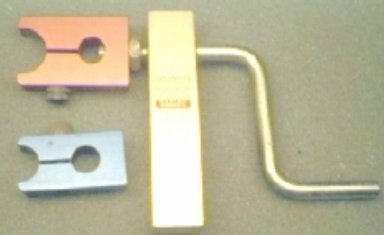
Armature winder..
A leftover from the slot car fad, this simple winder mounts in a vise. The 2 clamps can accommodate armatures in the 1/2" and 3/4" ranges.
Until recently with the introduction of rare earth magnets, the other alternative of increasing flux was not feasible. Two types are fairly common in surplus with much higher field strengths than either alnico, ceramic, or ferrite . Samarium cobalt has about 4 times the strength, while neodymium iron boron has about 5.6. Like ceramics and ferrites, a major advantage is retentivity is not dependent on removal.
The critical dimensions that determine total field strength are the length between poles and the cross sectional area perpendicular to it. With practically no loss, close fitting flat types can be stacked to attain length required in open frame motors. Due to curvature, can motors do not lend themselves to modification easily.
For analysis and comparison, doubling the flux will be used. With no other changes, torque will double and RPM will halve.

Note: Adjust brightness and contrast for optimum viewing.
Graph with flux doubled.
To the same scale as the original, the width should be doubled and the hight halved. The power does not change. Efficiency will increase slightly due to decrease in no load current. Usable values are, 4 K - 2.5 K RPM, 1.8 oz-in, 6 MP. At the continuous load line, RPM halved and torque through to drivers doubled as it would by doubling the gear ratio; but without the possibly extra friction losses.
With samarium a 18 K motor similar to a PM-1 would produce 4 times the original torque at 4.5 K, while for neodymium the values are 5.6 and slightly less than 3.2 K. In a Mantua RDG A-5 Goat, the latter would produce a top speed of about 17.6 SMPH. In a practical case, stacking magnets and fitting may produce a smaller ratio. Assuming a ratio of 5, would yield 20 SMPH and more torque than could ever be used. The only foreseeable problem is increased cogging due to low RPM.
Developing improvements on existing non-replaceable motors remains difficult in many cases. Enclosed can motors provide little possibility for fine tuning or improvement. Open frame types permit truing commutator, adjustment of brush contact pressure and magnet replacement. The major problem is finding suitable sizes to replace existing motor magnets. Basically consisting of what appears to be a ceramic type material, they are very difficult to shape and can be shattered very easily. When I can hire an inexpensive diamond cutter or can take lessons from one, more trials will be made.
As a step closer to a super motor, Bowser recently released a SKEWED DC-71 _open frame version with new magnet material, for upgrading many older locos.
Recently sources for cubical neodymium iron boron (NdFeB) magnets were found, unfortunately some needed sizes were not. An available .5 x .5 x .5 " almost fits and was tried on a relatively simple CONVERSION OF A PITTMAN/BOWSER DC-60 . This was tested on an old PENN-LINE PRR H9 . Results were not exactly what was expected from theoretical analysis, however improvements were impressive. Observation shows that much of the flux escapes the pole piece path and does not contribute to the output.
Other results are listed in MOTOR EVALUATION
To test the results more thoroughly, a new dynamometer design has been drafted in XCAD. It will measure current, RPM, plus stall and running torque to determine power and efficiency. Its use should dispel some common misconceptions and hype about comparison of various types of motors. It is in the construction stage with some delay in obtaining parts. The tachometer and stall torque portions work well, but due to an oversight in computing the running torque drum, the diameter had to be reduced drastically. Readings are now in the ballpark, but need refinement. After over 40 years of disuse, my education in physics (mechanics) is a little rusty in this area. When complete and tested, an article on fabrication and use will be posted.
Some tests were made with the working portions of the dynamometer in development. Noload RPM was measured on bare motor with a laser tachometer. Tests were run at the 12V standard and at 5V to examine low voltage operation. The motors were those readily available and limited to those that may fit HO locos with only minor surgery. The idea of tearing locos apart was not appealing. Power is calculated using the abbreviated method at the half stall torque point as shown in graphs above. The results are presented in tabular form in STALL TORQUE TESTS for your own evaluation.
results, in stall torque and current, reveal surprising results in comparing magnet upgrades and some common flat can motors.
Under investigation, another possibility to improve open frame motors is to skew the armature pole pieces without upsetting the relationship to commutator segments or damaging the windings. Twisting the laminations may loosen them on the shaft or create shorts through the insulation separating them, increasing eddy currents. Another idea is to place permeable tapers at the rims of the slots without shorting the laminations.
BACK TO MOTOR GRAPHS
BACK TO MOTOR EVALUATION
BACK TO REMOTORING
BACK TO REMOTORING SKEWED
BACK TO REPOWERING KNOW WHY
