Has a neighbor's kid ever asked you, "Hey, Mr., how fast can you make your train go?" You shuddered knowing full well what he meant. Can you run your prized Podunk Limited, with over three thousand hours of assembly, detailing, painting and lettering, fast enough to derail it at the next curve and smash it into the wall? Or better, hurtle it to the floor resulting in a pile of junk?
Seriously how fast do they go? Did you know in HO that cute little 0-4-0 camelback switcher can do 104 smiles/hour at 12 V. or the most popular diesels on the market can top 140 with the old motors or 110 with the new? Some of the Hong Kong specials can hold their own at over 200, only exceeded by the Hi-F rubber band drives at ?? I can't keep them on my 34 in. radius test track to find out. What does this mean to the serious modeller? The main objective should be to make the pike believable. Is this?
Look at the prototype to find out. First use the old rule of thumb for steam, based on rod strengths and weights, and balancing problems. Prior to about 1890, the maximum loco speed was expected to be 0.75 times the driver diameter or 80 in. drivers yielded 60 mi/hr. Around the turn of the century, the expected speed was equal to the diameter or 80 in. = 80 mi/hr. After about 1910 the expected ratio was 1.25, or 80 in. = 100 mi/hr. Like all rules these were usually broken. One account claims Pennsy's E-3d 4-4-2 #7002 hit around 129 mi/hr hauling the Pennsylvania Limited while making up time. This is about a 1.6 ratio. The Pennsy N-1s with 62 in. drivers hauled ore trains at 35 mi/hr. While all those switchers with 50 to 56 in. drivers operated in yards with speed limits of 15 mi/hr or at most in cities with a possible limit of 30 mi/hr.
Locos without side rods like, diesels and electrics, were limited by other problems such as dynamic augment or rail pounding, so diameter and speed relationships did not hold true. Only gearing made the difference.
How do you find out what normal speeds were? From books about your favorite railroad, time tables, loco spec sheets etc. and a little common sense. NMRA Data Sheet D4d has a good discussion.
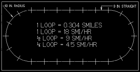
Now consider the other major factor: the layout. Examine an almost unbelievable example, the most common starting layout: a 4 X 8 sheet with an HO train set's snap track stretched out with a few 9 in straights added to the 18 in curves to make the largest loop usable. This empire consists of about 0.3 smile for one lap. (SMILE = SCALE MILE=60.23 feet in HO)
Since 60 mi/hr = 1 mi/min = 1 mi/60 sec, it only takes 0.3 X 60 = 18 seconds/lap at 60 mi/hr. While at 180 mi/hr it only takes 6 seconds. Time does not scale down with the models unless you use a "fast" clock. What to do? A lot of things like build a bigger pike, regear and/or remotor your locos or just make believe. Before doing anything, know what speeds you have the easy way.
Understanding what speed is might help in learning how to measure it.
Driving at 60 mi/hr, if you travel for 2 hours you cover 120 miles or for 1/2 hour only 30. Now the hard part: if it takes 35 minutes to go 15 miles, how fast did you go? Let's take a one minute course in Physics, limiting the snow.
Speed is the distance traveled divided by the time taken.
How do we use it? Plug in the above numbers.
S mi/hr = 15/0.5833 = 15/(35/60) = 15 * 60 / 35 = 25.71 mi/hr
A minute is 1/60 of an hour, so we must divide by 60 to change to hours. The magic in bold type is based on the rule: to divide by a fraction you invert and multiply.
Since distance and time can be measured in many dimensions, look at some that are useful.
60 mi/hr = 60 mi/60 min = 1 mi/min = 5280 ft/60 sec = 88 ft/sec
1 mi/hr = 5280 ft/60 min = 88 ft/min = 12*88 in/60 sec = 17.6 in/sec = 17.6*2.54 cm/sec =
44.7 cm/sec = 44.7*60/100 = 26.8 m/min = 26.8*60/1000 = 1.61 km/hr
These also hold true in the scale world using smiles etc., but remember time is not scaled. The hard part is to know when to multiply or divide and the sure way is to get a feel for it.
Driving on the interstate at 60 mi/hr, the time between mile markers is close to a minute. The average coupled length of later steam era freight cars was close to 44 ft, so 2 cars should pass per second at 60 mi/hr. Passenger cars are close to 88 ft coupled length, so 1 car passes per second at 60. This holds true on the prototype or any scale, though not too useful yet. Look at this:
Idea: count cars for 1 minute. But, how many trains have 60 passenger cars to get up to 60 mi/hr? So count for 1/10 minute or 6 seconds and then multiply the number of cars, even half cars, by 10 to get a good estimate within 5 mi/hr. The trouble is counting seconds and cars at the same time. A timer or buddy helps. Freights work well with steam era cars, just divide the number of cars in 6 seconds by 2 and multiply by 10 or just multiply by 5. Modern freight cars do not average to 44 ft with all those 86 ft hi-cubes, tanks and TTX flats. Forget it.
There are only two "scientific" ways to derive speed: fix the distance and measure the time or fix the time and measure the distance.
First fix the distance.
Driving slower than normally on the interstate, a stop watch counts 90 seconds between mile markers.
1 mi/ 90 sec = 60/90 mi/min = 2/3 mi/min then
s = 60 mi/hr * 60 /90 = 40 mi/hr.
Think about it. It took 1.5 or 3/2 times as long as 60 mi/hr so your speed was only 2/3 of 60 or 40 mi/hr. So it works.
Now fix the time.
Using a timer set to 60 seconds, count the 0.1 mile markers. The minute count is 12 posts or 1.2 mi, so:
Hey, what are those flashing lights?
This introduces another idea in that speed comes in two flavors: instantaneous and average. Theoretically instantaneous occurs only when time is zero or practically, very short near zero. In all other cases, we obtain average speeds. Normally the closest we get to instantaneous is by using a speedometer. Why not just use a speedometer? Its easier? Not so fast, those used in our cars are well known for their inaccuracies. First they depend on a centrifugal force against a spring and are rarely accurate at more than two points. The newer digital types eliminate this problem. But there are wheel slip, tire wear and inflation for which they can not compensate.
Look at some prototype loco pictures later than the fifties. Notice a little box with a cable on one of the pilot wheels or idler wheels on diesels. The box counts revolutions of the wheel, which are distances around wheel tread, and a micro-computer displays the speed in the cab. Since slippage is eliminated and inspectors check tire wear closely, this one works well. But these don't fit in our models. Radar and Vascar do not work well at these scale velocities.
By examining different methods with their pros and cons you can select one that meets your needs and budget.
As advertised, speedometers look like a good choice. Honestly I have never seen one that works and though I am a thoroughly experienced electronics design engineer, none of my many attempts to make one that does were successful. In spite of improvement in solid state devices over the last 30 years, the designs never got off the breadboard. Measuring track voltage alone will never make a speedometer, since at a given voltage speed will vary with load, motor, gear ratio and driver diameter.
Available in any good hobby shop, an inexpensive model airplane tachometer might make a good starting point to copy the prototype speedometer. A photo-cell generates pulses from light reflected from shiny spots and a counter outputs RPM. I use one to check RPM of jig mounted motors with a calibrated disk on the shaft. Maybe more on this in a future article. A speedometer would be possible , if the photo-cell could be mounted next to a wheel and there were a way to send the pulses to the tachometer on your control panel, but problems exist.
A well known fact in prototype loco engineering is: if a loco with 80 inch drivers does 80 mi/hr, axle rotation is very close to 336 RPM = 5.6 RPS. This is very useful when regearing.
(Driver diameter inches)mi/hr = 336 RPM = 5.6 RPS
But driver revolution is not useful because of slippage.
A 33 in. idler wheel at 80 mi/hr would rotate at:
80/33*336 = 814.5 RPM = 13.6 RPS.
But at 8 mi/hr yields:
8/33*336 = 81.5 RPM = 1.36 RPS.
There are not enough pulses.
The count could be increased by placing dots around the wheel. But how many photo-cell readable dots can be accurately placed on that little wheel?
Try the motor shaft, that's rotating much faster. Now the problem of different gear ratios and driver diameters is introduced. The ratio for each loco has to be determined and the tach has to be set for each different loco with a many poled switch. The final problem is to make a transmitter and receiver to get the pulses from loco to panel.
Commercial attempts at speedometers have occurred. Several years ago electronic wizards discovered that a five pole motor generates 10 current pulses per revolution and these can be seen right at the power pack with an oscilloscope. Using these could eliminate the problems of transmitter and receiver, but not the gear ratios, driver diameters and slippage. A motor turning at 10,000 RPM would give us 10,000 X 10 / 60 = 1666.67 PPS. Switching would be required for 3 and 7 pole motors.
The major problem is pulses are produced by standard power packs at 120 pps and 60 pps on pulse power, while fancier packs have adjustable rates from 0 to 600 pps. Arcing motor brushes and pickups can produce from 0 to billions of pulses per second. Watch some of them on your TV. Considering motor PPS varies with speed from zero to about 2,000 and the amplitude varies with load, standard filtering techniques to eliminate the undesired pulses fail to yield the desired pulses.
Would this tell us what we want to know? Since no layout is perfectly level and most have curves and no loco has perfect pick-up and gears bind, the speeds could be erratic. Even worse if the drivers were slipping you may never know it. Instantaneous speed could be confusing and downright misleading. So much for speedometers.
Before digging into the simpler and more practical methods, consider some tools that may be needed.
First a stop watch, a count down timer or a chronometer digital watch. Nothing fancy, but the digital ones are cheaper and easier to use.
Next a measuring stick or tape divided into 1/10 inches, if you can find one. Feeding decimal data into the next tools is much easier. Familiarity with and use of the metric system, eases the problem.
Tools? Yes, the best tool you can have, if you learn how to use it. A pocket calculator with ¶ (pi) so you can figure the distance around the circle of track, once you measure the diameter. Up a step is one with one or more storage memories to avoid writing on paper and reentering data. Handier is a programmable one, if you plan to do a lot of work. Best and my choice, is a pocket computer-calculator combination, once you learn to program it. Decide later what level you feel you need. The second part of the article THE COMPUTER APPROACH will be devoted to using (pocket) computers.
A little preparation is necessary to get on the right track.
First, since everyone is not in HO, scale factor "F" must be defined.
FO = 48____FS = 64____FHO ~= 87.1____FTT = 120____FN = 160.
If your not listed, you can find yours in the NMRA Standards. This is the ratio of the prototype to your scale. Next we define a term coined many years ago: a SMILE or scale mile in real feet and inches.
1 smile = (5280 / F) feet = (5280 * 12 /F) inches.
O smile = 110 ft = 1320 in.
S smile = 82.5 ft = 990 in.
HO smile = 60.62 ft = 727.4 in.
TT smile = 44 ft = 528 in.
N smile = 33 ft = 396 in.
Look it over because you will be using yours later.
NOTE: Although "Large Scale" runs on NO. 1 Gauge track, F varies inconsistently from about 22 for narrow and odd through to 32 for standard gauge scale models.
Go back!
Now for some more practical methods.
To use most methods it is necessary find out how many smiles are in a test loop of track. The example uses HO snap track on a 4x8, but the method works for any scale and flex track as well with a little juggling.

First take a full circle of the track and measure the diameter in inches using points half way between the rails. That is where the radius of a curve is taken. The nail holes in snap track ties are on this center line so use them as a guide. In this case d = 36 in. So the length around the circle or circumference ( ¶ = pi)
C = ¶ * d = 3.1415927 * 36 = 113.1 in.
Having ¶ on a calculator makes this easy. Write it down or store it in memory.
Next measure the length of a straight section, which should be 9 in. In the example 6 straights fit lengthwise and none crosswise, unless you like to live dangerously. There will be 12 by count, which yields: 9 * 12 = 108 in. Add this to C to get L = 221.1 in,
The loop is L = 221.1 / 727.4 = 0.304 smiles.
Round this off to 0.3 smi. to make things easier. This introduces an error of about 1 %. But who can eyeball the difference between 99 and 100 MPH.
NOTE: To those using imported track, measure to be sure. N scale 9 3/4 in radius is really 250 mm = 9.84 in and not 9.75.
NOTE: To those using flex and odd shaped loops. There are two solutions. Measure the loop distance with a wheel type "measurer" or determine the number of ties/length of a full section. From this get the ties/inch. Multiply the number of full sections by ties/section. Then count ties in odd sections and add them in. Now divide ties/in into the total number of ties to get L in inches. It will not be perfect, but it will be close enough for practical purposes.
Now comes the fun, what do we do with it?
First fix the time and measure the distance.
Remember: 60 smile/hr = 1 smile/min = 1 smile/min.
If you set your timer to 1 minute or 60 seconds.
1 loop/60 sec = 0.3 smiles/min = 0.3 * 60 smiles/hr = 18 smiles/hr.
Half a loop = 9 smiles/hr and a quarter = 4.5 miles/hr.
If a train makes 3 3/4 loops in 60 seconds:
S = 3 * 18 + 3 * 4.5 = 54 + 13.5 = 67.5 smiles/hr.
Not bad, for the price of a cheap timer and a little work we went from no idea to measuring speeds to within 5 MPH.
For closer speed, each track section past a quarter loop adds about 3/4 smi/hr. Anyone who can eyeball speeds that close is a lot better than I am. If you prefer 1 loop = 20 smi/hr, you could tear up the whole thing and use 22 inch radius instead of 18 and come close. Am I crazy?
Here is an easier way. If time were cut in half to 30 seconds the train would have to go twice as fast or 36 smi/hr to cover the loop. Decreasing the time requires the train to go faster to cover the same distance. Time is not sacred, it can be adjusted. Using the above:
1 LOOP/ 30 sec = 60/30*18 = 36 smi/hr
Solving for time: T = 18 /36 * 60 =30 sec
To find the time adjustment for 1 loop = 20 smi/hr:
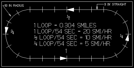
time = 18 / 20 * 60 = 54 sec.
Using 54 sec,

1 loop = 20 smi/hr, 1/2 loop = 10 smi/hr, 1/4 loop = 5 smi/hr
making computation easier.
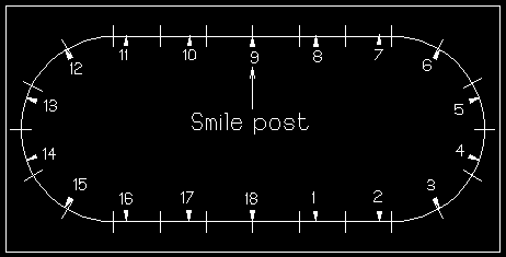
For greater accuracy emulate the interstate and plant smilage markers around the loop. Remember: 1 smi/hr = 88 sft/min. There are close to 18 of these 88 sfeet (Its easy to pronounce if you speak Italian.) lengths around the loop. Do not try to measure them, there are not exactly 18 since the loop length was rounded off. Just count all the ties and divide by 18. Straights have 31 and curves have 34. Total = 31 * 12 + 34 * 12 = 780 ties. Marker distance = 780 / 18 = 43.33.

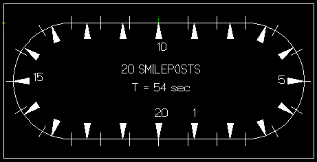
Wait just a cotton pickin' minute, who's gonna eyeball all those 1/3 tie spacings. This is another good reason to adjust the time to 54 seconds. Then you have 20 lengths around the loop, thus marker distance = 780 / 20 = 39 ties. Now you can add even smi/hr onto your 1/4 loops. Understanding what has transpired should enable one to adapt the ideas to one's own scale and loop.

Now for those who don't like to count. A slave is available to do the counting: A digital counter, already made up for just over $100 or roll your own for about $30. All that is necessary is to replace the smilage markers with sensors between the rails, do a lot of wiring and come up with a gating circuit to feed all the pulses into the timer. All the hows will not be covered, since this not intended to be an article on circuitry and there have been articles covering the subject in the past, some with shorter lengths of track similar to the old road speed traps. But the idea is the same. Information on counters can be found in Radio Shack's engineering notebooks and deeper coverage in Howard W. Sams' how-to books. Making your own, however, allows time adjustment, while the commercial counters usually have fixed decade or 1-2-5 settings.
There is one possible source of error in the timer methods. If the loop is not really level and the distance traveled is not whole loops, there could be more up-hill (slower) than down-hill (faster) time or vice versa. If bad enough accuracy could thrown way off.
By fixing the distance to a complete loop, the up and down problem can be eliminated. In fact an unlevel loop might give a better picture of the overall performance of a loco. Here the time around 1 full loop is measured with a stop watch. Review the loop again. Remember S = D/T. So the time must be divided into the distance. This is where the calculator comes in handy. But the stop watch counts in seconds, so another magic number is needed to convert.
1 loop/min = 18 smi/hr so 1 loop/sec = 60 * 18 = 1080 smi/hr
1080/60 sec = 18 smi/hr. 1080/30 sec = 36 smi/hr. 1080/120 sec = 9 smi/hr.
Juggling the stop watch and the calculator may be a problem. Enter the magic number, read the stop watch and divide the time read into the magic number. Now read the speed. If the watch reads to 1/10 second, how accurate can you get?
Reading the calculator the loco may be speeding along at 63.763904578 smi/hr. Great! That is more accurate than the time trials at Indy. Not so. Even an expert at using a stop watch is lucky to get within 0.1 sec of the true time.
Proof: 1080/60.1= 17.97 smi/hr. 1080/59.9 = 18.03. The spread is 0.06 and both round off to 18.0. So only 0.1 smi/hr is really the accuracy. Better than counting smileposts?
There must be an easier way. There is. A sensor could be put in the track to turn a digital stop watch on and off by jumpering into the start/stop button wiring. Most commercial digital counters provide a timer feature with external triggering. Now it could time down to 1/100 sec or closer. But that dividing part! Get a calculator with a memory and stick 1080 in it. All that is necessary now is pull it from memory and divide the time into it. Better but not really good. It lacks a genius to design a device to move the time into the calculator.
There have been several articles covering calculator to stop watch conversions. These feed clock pulses to the (+) key wiring on calculators with repeat capability. If there is memory and a reciprocal key, once the timing has stopped, the magic number is divided into the result and the reciprocal is taken.
The only problem is that it takes 4 minutes at 5 smile/hr to cover the loop. But I get a kick from watching the damned things run. To avoid wasted time, pick any land mark as the start/stop point.
Better, for the additional price of a calculator , you can get speeds down to 1/10 smile/hr, if you have a quick finger and good judgement.
BONUS: You can calculate motor RPM from track speed.
That's it. You have two possible inexpensive ways to determine how fast your train goes. I prefer the latter because it is more truthful and adaptable to the next approach.
But there must be an easier way. TRY THE COMPUTER APPROACH
BACK TO MEASURING
BACK TO REPOWERING
BACK TO REPOWERING ANALYSIS
BACK TO REMOTORING
BACK TO LOCO TESTING
