Even on a sheet of plywood, an all too common occurrence is that of trains slowing unexpectedly at some point. This may be to voltage drop in long feeders or their lack; but more often it is caused by a grade, introduced from lack of proper leveling. Since most floors or ceilings are slanted for drainage, they are not usable for reference. On a large layout floors may vary by over an inch at the extremes. This can effect grade layout drastically. Since close to a 20' run is required on a 1.5% grade to rise 3.5" for HO overhead clearance, this would introduce an error over .4 %. Leveling methods may vary drastically depending on type of benchwork, from a sheet of plywood to L girders. For sheet plywood, one corner point can be set at the desired level and using a long bubble or spirit level, trued at right angles along edges. Check diagonally to be sure.
Open bench work presents problems, determined by type. With modular or boxed grid, each section must be leveled separately after establishing a reference point. Bubble levels may be used with smaller ones, but for large layouts the cumulative error may be worse than using the floor as reference. Linn Westcott's "L" girder is far easier to level, if the L's are reasonably straight on top. During construction each leg is clamped until final adjustment.
An easier way to establish zero level and others derives from Bernoulli's statement that water always seeks its own level. This is true for connected bodies of water at reasonable distances, regardless of complexities, contours, shapes or sizes. Water and some other fluid(s) level indicators used on boilers and tanks are based on this principle.
A very simple device can be made by connecting a plastic bottle through a length of flexible tubing to a clear length of sight glass, rigid tubing. Through its use any level may set, at any time, anywhere in reach, include at risers and cleats. The only limitation is that the tubing length must be long enough to reach, with enough slack for adjustment movements. Both ends must be open to the atmosphere to eliminate any vacuum effects. The bottle may be any convenient translucent or clear, soda, milk or similar container; taking into account that it will be semi-permanently mounted somewhere, out of the way, at the zero level. Size is not critical, but it should be large enough to prevent overflow, if tube is transported at hights greater than top.
In the plane section of good hobby shops, along with the matching tubing, puncturing fittings for plastic fuel tanks are readily available to aid tube connection. If you must buy a fuel tank to get fitting, select a long one that may be used as bottle. Use the largest size fitting and tubing available to reduce capillary effects. Purchase enough to reach from bottle location to any point on the layout, with some extra to work around obstacles. Place connection on side of bottle, a short distance above bottom, to prevent any sediment from entering tubing. Although not an absolute necessity , if flex tubing is clear, a short piece of clear, rigid tubing improves function. It must fit snuggly inside the flex with no leaks. With care, glass tubing from the chemical section can be used. To hold sight glass, a bendable hook of bailing wire is useful, unless you have three hands. Most important, a permanent, visible, reference ring must be marked around tube. With extreme care this may be done with a small modeller's tubing cutter. If long enough, additional reference rings may be added.
Water tube level. Not to scale.
Select a location and mark the zero level on the wall or post, so that it will be clearly visible and accessible when bottle is mounted. Consider your mounting method and light source. This line will be your permanent reference. Other markings may be added above or below to reference other levels or a clearly visible scale may be affixed. The mid-height of the bottle should be at the reference line to permit water level fluctuation. By fixing the bottle on a back plate with mounting hole(s), the assembly may be moved vertically for hights beyond bottle length.
Once assembled and mounted, securely place the tube reference ring on the desired permanent reference line. Then fill the system with water through the bottle top until level aligns with the tube reference. After settling for a time, check for air bubbles, and remove by juggling and shaking tubing to work them out either end. Due to surface tension, in any container, water forms a concave meniscus, since it tends to climb the wet walls. This must be considered in establishing your level. Choose the point most visible to you and use it consistently. The amount may be very different between the bottle and the tube, due to their diameters. The tube level is the critical one, while the bottle level is of no consequence except for an occasional check for evaporation. Other level settings are easily attained by adding water at the top to raise or removing by spilling water from the tube to lower. It is now ready for use.
There are some other things that may be considered. In some hard water cases, the solutes may coat the sight tube. A small amount of detergent or water softener may help or distilled water may be used. When using well or other untreated water a few drops of bleach can help retard fungus and other growths during storage. Care must be used in the use of dyes to improve visibility, since some may stain sight tube walls. The bottle cap and a plug or cap at the tube end will reduce evaporation during storage.
Use is simple. Just fasten sight tube reference on point to be set and adjust benchwork height until water level lines up with tube reference. Since water has a viscosity, which slows movement through tube, allow sufficient time for settling, after each change. Once a known level is established on benchwork, others may be measured from it, in the immediate vicinity with very little loss in accuracy.
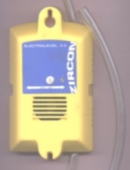
Recently electronics has entered into the field, with the introduction of a system with an audible level indicator and a sensing unit replacing the bottle. Tubing extends from both ends of unit and clamps are provided to seal ends for storage or relocation. Long term storage with water in contact with sensor may cause corrosion. A bottle brush is provided for cleaning.
Note: Adjust brightness and contrast for optimum viewing.
Audible level. Zero reference in side notches.
Usage is similar, but some procedures are changed. The sensing unit is fastened at the desired reference mark and must be moved to change level. Mounting does not permit easy movement for adjustment. Then the sight end of the tubing is adjusted until sound is just emitted on the upward movement; at which point, the water level is marked on the tubing. This requires a new tubing reference mark after each change in reference level or after any evaporation during storage. Fastening to benchwork is not practical , since correct sensing is only on upward movements. A vertical stand could be devised to hold sight end reference adjacent to bench work, while adjusting. The accuracy is purported to be less than 1/16" error at 50'. This would yield a 20' grade error of less than .03%. A fair amount of practice is required to enable duplication of settings.
The home made unit is far less expensive, at least as accurate and much easier to use.
Sighting with various surveying instruments to establish levels is common, but expensive and impractical on layouts. Using light beams does not work too well, since there is a tendency to spread, due to frequency band width. More recently monochrome lasers have reduced the problem. Once very expensive, they are now very affordable. A $10 LASER LEVEL could solve many layout levelling problems.
BACK TO MEASURING INDEX
BACK TO TIPS ON TESTING
