Today meters come in analog or digital types, each with its own applications. A good multimeter with AC and DC; volt, ampere and ohm scales is a excellent general purpose tool. Even a digital readout oscilloscope makes a handy meter for special cases. For most modelrailroad applications analog is better, since indications are steadier. Digital types react too quickly, causing digits to jump around wildly under standard test conditions. An accuracy of less than 5 % is usually sufficient for most tests. The faces should be large enough to read easily with illumination, if used in dim areas. Most generally available analog meters are based on DC ammeter movements in the micro to milliamp range. External circuitry (resistors , rectifiers) determine their usage. With modified scale numbers, they can be setup for a wide range of voltages or currents.
AC meters usually have a modified rectifier bridge to convert to DC required by the meter movement.
SOLDERING is highly recommended for permanent connections used with meters to avoid damage by opens or shorts by loose wires or junctions .
OHM'S LAW
To roll your own, the variations of this law are an absolute necessity. E = voltage in volts. I = current in amperes. R = resistance in ohms. P = power in watts. Since these are metric values, the standard metric prefixes apply. When any two of these values are known the others can be derived.
E = I x R __To find voltage .
I = E/R __To find current.
R = E/I __To find resistance.
P = I x E __To find power.
P = E^2 / R
P = I^2 x R
NOTE:One bit of knowledge rarely taught, but quickly learned by novice circuit designers is that mathematically derived component values are almost impossible to find. Most have tolerances of 5 or 10 %, while more expensive 1% values are not uncommon. In general most come in a standard series, which at first may seem odd. In most cases, the closest value is selected and usually works. In more critical cases, selection is made from a batch by measuring value with accurate test equipment. (Ohmmeter for resistors ). Components may be combined is series or parallel to achieve a closer total value. In very critical cases a low value trimmer (variable) is used to adjust to a more exact value. Elementary electronics manuals usually discuss these circuits in detail with examples.
METER MOVEMENTS
Some basic concepts should be understood. Full scale deflection (FSD) is the maximum value for the scale and meter. Mid or half scale deflection (HSD) is exactly half the value. This is the point usually used for calibration to avoid pinning needle, because initial test readings may be higher or lower than expected. It may improve accuracy of most readings, which are probably near the middle.
Scale should be selected so that divisions are even values for easier reading. If you have a good drawing or CAD program you can make your own.
If you buy a movement, (ie. from Radio Shack) it should be marked on the face or back with the fullscale current (1 ma) and resistance (87 ohms). From this the voltage drop across it is:
E = I x R = .001 x 87 = .087 V = 87 mV
Thus we know all three values to be used in "making" a meter.
Unfortunately not all movements are marked with their resistances, but fortunately they can be found using a dry cell, two potentiometers, some jumpers and possibly a switch.

Choose a 1.5 V dry cell and a 1 mA movement. Estimate R1 minimum value with switch open.
R1 = E/I = 1.5 / .001 = 1500
The closest common value is 25K ohms. R2 could be 500 ohms. Resistors can be added in series to raise values if needed.
Adjust R1 from maximum down to the point where the pointer rises to FSD (full scale deflection). Close switch and adjust R2 until pointer is at HSD (half scale deflection). Half the current is now through the movement and the other half through R2. Thus R2 = Rm. Open switch and measure R2 with an ohmmeter. Only a close approximation is needed as a starting point for the methods below.
 CAVEAT: Do not use an
ohmmeter or a bridge to measure movement resistance directly. These
may provide enough current to damage movement.
CAVEAT: Do not use an
ohmmeter or a bridge to measure movement resistance directly. These
may provide enough current to damage movement.
VOLTMETERS
Measuring various voltages can be very useful and revealing. The starting voltage of a loco indicates the quality of the motor and mechanism. The lower the better. The standard maximum voltage (12 V for most scale operation ) can be used to determine maximum train speeds. Half way between these values should be very close to half speed, providing a crude speedometer. During testing it can uncover shorts or opens.
To make a voltmeter from a movement, decide the voltage required. Most DC power packs output at least 16 V and possibly 20 v. To avoid pinning needle pointer by over voltage and since scale is graduated from zero to 1, 20 v is a good choice. The 5 marked larger divisions will be at 4 v intervals.
resistance in ohms
Voltmeters have a resistor in series to limit the current and drop the voltage across the movement. The circuit is a basic voltage divider. To determine the value, there are two approaches.
From the movement current find the total resistance for 20 v.
RT = E/I = 20 / .001 = 20000 = 20 K ohms
Subtract the movement resistance to obtain the value needed.
RS = 20000 - 87 = 19913 ohms. Your not going to find one. Using 20000 the error will be much less than you can eyeball.
Error % = 87 /20000 * 100 = .435 % The second approach is to subtract the movement voltage from the total and divide the result by the FSD current.
RS = (20 - .087) / .001 = 19.913 / .001 = 19913 ohms
Check by comparing reading to a good quality meter (100 kohm / volt or better). Try different resistors, since even 1% resistors vary in a batch, If closer calibration is necessary a string of resistors adding up close to the theoretic value may be assembled, adding or dropping small values to correct or by adding a a 5k potentiometer in series with an 18k. Using a switch, different values may be substituted for different range.
AMMETERS
Ammeters are very useful in both testing and during running. The most important indication is that the motor's maximum continuous current is not exceeded for any extended time to avoid over heating or burnout. Current draw is an excellent index to a loco's condition and performance with or without a train. For serious operation, they are a must.
These are a little trickier in that a very small resistor (shunt) must be placed in parallel (across) the movement to carry the excess current. This is a basic parallel resistance circuit, Assume a 5 A meter. Again 2 methods are available .

Find the excess current by subtracting movement from the total and divide this into the voltage across the movement.
RS = E/I = .087 / (5 - .001) = .087 / 4.999 = .0174 ohms
Or take the current ratio and divide it into the movement resistance.
Rs = Rm / (Is /Im) = Rm * Im / Is = 87 * .001 / 4.999 = 87 / 4999 = .0174
Or simply the current ratio is very close to 5000, so just divide the movement resistance by the ratio:
Rm = 87 / 5000 = .0174
NOTE: For small multiplier ranges such as 10 mA, the shortcut may introduce a large error. The shunt will carry 9 mA for a ratio of 9, yielding 9.67 ohms and not 8.7 hms with about a 10% error.
First measure the distance between movement terminals. Add about a1/2" for hookup error. Assume 2". The resistance per inch is .0174 / 2 = .0.0087. Using a wire resistance table, look up values for some common solid wire sizes you have. These are usually given in ohms per 1000 feet. Multiply .0087 by 12000 = 104.4. Pick one that is less than 104.4. Number 30 is 103.2 ohms/1000' = 103.2 / 12000 = .0086 ohms / inch , which would require about 2.02". Using #28 = .0054 at 3.22" and #26 = .0034 at 4.32". For 1 A five times the length would be used, since only 1/5 the current is shunted. Extra wire can be coiled around scrap plastic later, if necessary.
To calibrate a current source and an accurate ammeter standard are required. The source can be a large rheostat power pack, if used with care. Since most output about 16 V with a 50 ohm rheostat in HO the current would be:
I = E/R = 16 / 50 = .32 A.
Cut wire a couple of inches longer than computed to allow possible lengthening . Prepare the new meter by permanently fastening one end of shunt wire and fix the other end securely, at the computed length, with a clip or screw it down.
Leads with alligator clips are very handy at this stage. Determine the polarity of the pack's terminals, hook a black wire to the negative to mark it and connect it to the negative of the standard meter. Do not change this or any polarity switches. Connect a different color wire to the meter positive. Switch on pack and crack open throttle to the lowest position, then while watching meter quickly touch lead to pack positive. If needle does not swing rapidly or pin, you are safe. If it does, get off immediately. Recheck connections and knob position..
With lead connected, very carefully and accurately adjust throttle to some convenient current about 2 to 2.5 V. Mark the position. Turn off pack and turn throttle to lowest position again.
WARNING: Shunt should be
securely connected to both movement terminals, whenever current is
applied or the movement may be ruined.
Move standard's positive lead to new meter negative. Connect lead to positive, switch pack on and quickly touch loose end of lead to positive as before. This time watch new meter for swing or pinning. If none, clip lead on and advance toward mark while observing new meter. Adjust to your selected value on standard and check value on new meter. If too high, shorten shunt slightly. If much too low, lengthen slightly. If only slightly low, after switching pack off, secure loose end to terminal. Switch pack on and with the back of a #11 blade, carefully scrape wire until reading is correct. Do this over a length, not likely to short to anything ,Secure the loose wire to prevent shorting to itself or anything else.
MULTI-AMMETERS
Shunts can be switched to provide dual or multi ranges. The major problem is switch contact resistance , which even on good quality switches may be in the same order of magnitude as the shunt. When added to the shunt resistance , this could drastically change the total. Worse the resistance is rarely constant and could be quite high or infinite, if the switch becomes defective, thus ruining the movement.
There is a solution, at a slight loss in sensitivity and voltage drop. By adding a resistor in series with the movement to add up to about 200 or 300 ohms, the shunt resistance will be at least doubled or tripled, reducing the contact resistance effects.

The ranges in the example are .5 A, 1 A and 5 A with a total movement resistance (Rt) of 200 ohms. For smaller scales ranges of .1 A (100 MA), .5 A and 1 A. might be chosen. There are other configurations for the shunt, but this one permits separate calibration of each.
The basic procedure is the same as above, but since we are looking for ballpark starting values, simplify computation a bit. The shunts must carry very close to 500, 1000 and 5000 times the current of the movement. Dividing these into the Rt = 200 ohms yields .4, .2 and .04 for the shunts respectively.
Select wire as before, considering switch to movement distance. Plan routing to avoid shorting wires to each other and themselves. Insulation may be added later if necessary. Be sure the switch is included in the circuit during calibration.
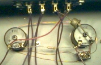
INTERIOR OF TEST PANEL SHOWING COMPONENT LAYOUT
Since this panel is used to evaluate external power packs and track test locos, a 10 A diode is wired in series to protect meters from reverse polarity. Ammeter is on right with 1 A | 5A shunt switch below. Two uninsulated wires from movement to switch make up 5 A shunt. The insulated magnet wire, 1 A shunt is looped around meters and switch to keep it in place. A movement series resistor was not necessary, due to the superior quality of the switch.
The voltmeter is on the track side of diode and ammeter to eliminate effective error from voltage drop across them. One track lead is wired from trackside ammeter junction to reverse and selection switches below, while the other is connected to the left terminal of the voltmeter. The series dropping resistor is between meters.
If meters are attached to power packs, lights may be added easily for dim area viewing by tapping into the fixed outputs. In some cases they may be mounted inside the meter under the face shield. If LEDs are used appropriate regulators and DC must be used.
For critical bench testing, circuitry work and calibration a good quality digital multimeter is invaluable. With FET inputs the ohms/volt rating is very high, practically eliminating any loading effects, when measuring low or accurate voltages. Current and resistance measurements are excellent for critical cases. Some have memories to store data for later comparison. Many have circuits and adapters for testing solid state devices as diodes and transistors.
An OSCILLOSCOPE is basically a time domain voltmeter which presents views of changes over a time period, from nanoseconds to several seconds. Triggering can synchronize the sweep presentation to events to select only wanted signals. They are particularly useful in evaluating pulses and waveforms of motor characteristics, power packs and all types of electronic circuitry, including computers. For modelrailroad purposes a less expensive 10 MHZ bandwidth should suffice. Expensive digital readout is very convenient for accurately measuring both time and amplitude.
Unfortunately it appears that too few of the designers and advocates of DCC and other circuits have the knowledge or experience to properly evaluate these products with a scope. There are too many surprises on evaluation, indicating poor design. My observations are based on almost fifty years experience in electronics as a technician, design engineer and computer system engineer.
With a little effort you should be able to test as well as the best of them.
BACK TO LOCO TESTING
BACK TO ESOTERIC TEST EQUIPMENT
BACK TO MEASURING INDEX
METHODS INDEX
BACK TO REPOWERING DON'T KNOW WHY
BACK TO REPOWERING TOP
BACK TO TOOLS INDEX
