Back in the 50's, these were offered at $7.98, with a 10.5 k RPM, side magnet open-frame motor, 13:1 gear ratio and 40" drivers, producing about 96 SMPH. Desiring to use these as industrial switchers, slowing was indicated. Applying a Jameco 231731CA motor at about 5 k RPM would yield about 46 SMPH and a lower current for those who desire it. Still a little fast for an industrial complex. Regearing with NWSL 24:1 worm and wheel would lower it to a more acceptable top speed of about 25 SMPH.

Note: Adjust brightness and contrast for optimum viewing.
ORIGINAL
Old motor visible through window.

Note: Adjust brightness and contrast for optimum viewing.
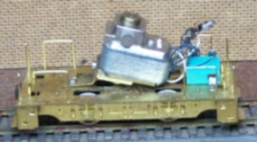
Old motor on left, new motor on right
As an aid to alignment, it is advisable to set up new motor with worm and to change axle gear before fabricating bracket. To pull the geared driver, remove one of the screws, that hold the frame rail to the floor, adjacent to the geared driver and loosen the other, to free the axle end from the journals. Since the drivers are fastened to the axle with nuts, the gear change is easy. Screw off nut and finger pull the wheel. Pull gear. Press on new gear. Place wheel on axle and secure with nut.
Because the new motor shaft was a little short and the NWSL worm fit loosely; for a more secure mount, a NWSL 2 mm to 3/32" bushing, partially filled with a short length of shaft rod was pressed part way into a 3/32" bore worm. This assembly was then pressed on motor shaft.
Sitting on the floor, the original motor was tilted with a bent bar, mounting bracket. A wide slot in the floor accepted the motor bell, but was too short to tilt the new motor enough to clear the hood roof to cab joint. To determine approximate angle, after lengthening with a large Dremel cylindrical cutter, to almost 3/8"; it was obvious that a new bracket had to be made. Several ideas were drawn with XCAD involving some fancy machining or bending. None was appealing. Finally a simple bar stock fabrication showed promise and drawings were refined.
Since the new motor bell is under 1/4", two K & S 1/4" x .032" strips were cut, bent and fastened to a plate made from 1/2" x .064" strip, cut to 3/4" long.

Note: Adjust brightness and contrast for optimum viewing.
BRACKET LAYOUT
Yellow line is bend.
Blue is end corner of motor.
Draw a centerline across the short width of the plate and cut a a 1/16" slot about .050 from one end. This should be a least 1/8" long to allow gear mesh adjustment. Deburr and test for flat and easy sliding. Test mount on floor using the 2 mm screw hole in floor. A second slot may be added, but was found unnecessary.
NOTE: Due to the difficulty in holding bar perpendicular and level to edge throughout entire length, the frequently recommended method, using the sharp edge of usung calipers to scribe lines parallel to an edge often creates wavy, inaccurate lines. A simple THUMB GAUGE can produce very accurate lines.
Some of the dimensions on the motor mount rails are critical to obtain good tilt and motor alignment. To obtain the correct angle of approximately 13 °, the strip must be bent .242" from the end, while the screw hole center should be at .121". This will seat the motor corner on the floor. Assuming the base plate was cut to .75". the longitudinal hole centerline is found from the motor mount screw center distance of 12.4 mm = .488" or .244 from the centerline. Subtracting this from the centerline to plate and rail edges, .375 - .244 = .131" from the rail outside edges. You might want to mark these to avoid confusion later. The overall length of the rails is not critical, but should not extend past plate and be long enough to permit positioning plate mounting screws in an accessible location.
Drill the motor mount holes to clear the 2 mm screws. The heads on most screws measured were too close to creating problems, so the holes were countersunk for flatheads. Check often until heads are flush with rail. All flatheads found were too long. Before using cutoff disk to grind to length, thread a nut on screw to clean threads.
Vee grooves, about 1/3 the thckness deep, were cut across rails at bend line to assure an aligned bend. This does not weaken bend appreciably. The NWSL Bender wedge fit nicely in these. Using a flat surface, check progress often by placing on plate until end just touches surface. Alternatively the bend cam be made by clampng in vise and lightly tapping with a hammer.
Mount rails on motor, assuring the flat is square with the rail outside edges. Mount plate on floor with screw at the slot midpoint and edges parallel to floor edges. Place motor and rails. If all went well rail outside edges will line up with plate. Slide motor for a good mesh. Mark locations for rail to plate screws. Remove rails and drill small holes. Place and align motor and rails again and, using the same bit, mark centers on plate. Remove and drill plate with tap bit and rails with a slightly large clearance bit. Screw together in alignment, then mount on floor. Minor adjustments can be made for proper mesh.
Lube and test at slow RPM. After determining correct polarity, one motor terminal was soldered to the can rim and the pickup lead was soldered to the other. Track test next.
The total weight was just under 5 oz = 140 gm , so lead weight was added in the hood areas.
