[ Current Projects | Hot List | Personal Interests | Contact Information | Encryption-Decryption software |
Karnaugh map generalization | Energy accumulation | Energy Density | Arithmetic engine | Astronomy Coordinates |
Curriculum Vitae | Home Page ].
Energy Accumulation
Energy Accumulation Techniques
Energy order of mass
(mechanical energy)
In this
technique, we will use magnetized blades as kinetic energy
quanta:
1. System items:
- Magnetized blades.
- Blades gun generates
blades at velocity v.
- Rubber strings
sheets as reflection planes.
- Continuous magnetic
field.
-
Pulse
magnetic field.
2. System
pictorial:

3. System functionality:
- Blades gun releases a
magnetized blade with vertical N-Pole (vertically
polarized blade)
- The released blade
with velocity v will enter in the gap between the rubber
strings that form the sheet (the blade is very thin and
the separation between one rubber string and the other is
large enough).
- The continuous magnetic field will force the blades that pass it to
rotate 90 degrees such that the N-Pole becomes horizontal
especially at the end of the magnetic field pole (it
gradients from vertical to horizontal).
- The horizontal
N-Pole blade will hit the rubber strings and will reflect
(it must collide with the rubber strings and then it will
repulse like a reflection).
- Then the blade will
continue in reflection along the four rubber strings and
it will loop there supposed that the velocity of the blade
does not damp.
- When the accumulated
kinetic energy of the blades is needed to be released, a
pulse magnetic field is applied such that each blade pass
beside it will rotate 90 degrees such that after the
blade reaches the end of the magnetic field pole it must be
vertically N-Pole blade again.
- All the blades will
leave the loop until the pulse magnetic field stop.
- The main constrain
on this procedure is that the vertically and the horizontally
N-Pole blades should not collide at the entering gate of
the rubber strings (at the blades gun end).
- For the blades to
traverse freely inside the loop, the blades separation at
releasing from the blades gun must be (it's constant
between each two blades due to the constant velocity v)
greater than 2L where L is the reflection volume of the
blade at the rubber strings. In addition, the reflection
time of the blade at the rubber strings must be zero.
- The loop length must
be 2mL where m is a constant and L is the blade length.
- When the blades gun
releases m blades, it will wait a time dt before it
releases other blades. For the loop length to be utilized
for high density, dt must be enough for a distance W
(blade width) under the velocity v, that is dt=W/v. After
a certain time, the blade density in the loop must be a
maximum and any additional blade will start preventing
correct reflection and will destroy the accumulation
system.
4. Accumulated energy: it's the over all kinetic energy of the blades.
Energy order
of electron (electrical energy)
In this
technique, we will use electrons as kinetic energy quanta:
1. System items:
- Evacuated tube.
- Reflection plates
(high conductive metals).
- Voltage sources.
- Electron boiler or
electrons source.
- Metallic thin rings.
- Metallic wide ring.
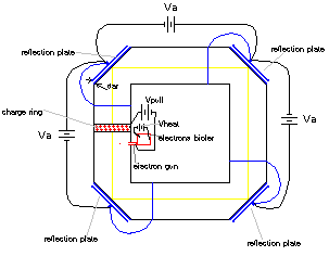
2. System pictorial:

3. System functionality:
- Electron boiler
generates an electron, using Vheater.
- Vpull pulls the
electron to the middle of the charge ring.
- Va, the accelerator
voltage, accelerates the electron until it hits the
faced plate.
- Before hitting, the
electron enhances some electrons on the faced plate buddy
because it passes through a metallic ring (induces
electrons).
- The reflection plate
has a buddy plate (they are like a condenser) ,
- The electron that
hits this plate will reflect.
- The process of
acceleration-reflection continues until the electron
jumps by it's accumulated energy to the initial source
plate and repeats reflection-acceleration.
- When the accumulated
beam needs to be released, one of the reflection rings is
disconnected and then the beam will puncture the
capacitor and leave the loop.
*One similar practical system is below (used mainly to
measure the reflectance ratio of electrons):
Va is very high, in the order of 10000
volts.
Conductor is of very small resistance in ohms. Wires must be cooled in liquid
Helium or another equivalent system.
Ring cylinders are thick conductive metals act as shields of induction of
electrons.
Thick sheet plates are conductive metal sheets forms a condenser like,
separation distance is very small. Area of such sheets is in 10s of centimeters.
The battery Va will inject electrons in the loop (I, II, III, Va). Electrons
will travel in wires at speed close to that of light, when the beam reaches the
plates it’ll try to turn 90o to continue on the next wire, this will
cause some electrons to enter the plate (consider it centrifugal force). The
ring cylinder will induce electrons in the plate which are enough to reflect
most of the entered electrons so that they keep traveling to the second wire
with small delay.
Condenser CIV will catch some electrons and will prevent them from
going to the source Va, instead they’ll continue with their kinetic energy to CI
during which the Va source can be balanced to substitute lost electrons, thus at
CI electrons (carriers) will be increased., another source Vs can be
used to accelerate electrons in wireIV if needed.
With time, voltage in the loop will be higher than that of Va, Va is considered
to be of fixed level.
The condenser Ca will hold the transient voltage increase and will decay it into
Va, a high voltage-current diode is used to prevent the decay such that the
voltage will accumulate into Ca and will be higher than Va.

Energy order of
photon (light energy)
In this
technique, we will use photons as energy quanta:
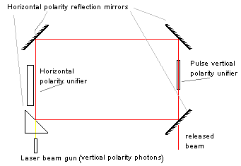
1. System items:
- Three reflection
mirrors for horizontal polarity photons.
- One prism, that it
is a mirror for horizontal polarity photons and a
transparent path to the vertical polarity photons.
- Continuous horizontal
polarity unifier for photons.
- Pulse vertical
polarity unifier for photons.
- Laser beam source,
it's a vertical polarity photons source with wavelength λ and frequency
υ.
2. System pictorial:

3. System functionality:
- The vertical
polarity photon enters the prism, when it passes
near-into the horizontal polarity unifier, it inverts to a horizontal polarity unifier.
- Next, the photon
will hit the mirrors and will reflect. It loops reflecting
each time it hits a mirror or prism.
- A horizontal
polarity photon does not effect by the horizontal
polarity unifier.
- With time, the
photons accumulated inside the loop. When it's needed to
release them , the pulse vertical polarity unifier will
invert each photon in the path to a vertical polarity
photon and so all the photons released until the pulse
vertical polarity unifier stops.
4. Accumulated energy :
- The accumulated
energy inside the beam is :

- The factor 5 is due
to that a four reflection volumes and one energy volume.
- If accumulation time
is large, the loop will destroy, the mirrors will no
longer react to the energy.


Back to Top
Eng. Ibrahim M. Hijazi.
Copyright © 2003 All rights reserved.
Information in this document is subject to change without notice.
Other products and companies referred to herein are trademarks or
registered trademarks of their respective companies or mark
holders.
For problems or questions regarding this web contact [femto].
Last updated: April 10, 2003.


