Dedicated to Really Cheap Audio Enthusiasts
| The Speaker Guy Dedicated to Really Cheap Audio Enthusiasts |
|||||||||||||||||||||||||||||||||||||||||||||||||||||||||||||||||||||||||||||||
| Low-Cost Satellite Speakers | |||||||||||||||||||||||||||||||||||||||||||||||||||||||||||||||||||||||||||||||
| Initial Design and Box Assembly | |||||||||||||||||||||||||||||||||||||||||||||||||||||||||||||||||||||||||||||||
| Finishing and Final Assembly | |||||||||||||||||||||||||||||||||||||||||||||||||||||||||||||||||||||||||||||||
| Machining the Baffles | |||||||||||||||||||||||||||||||||||||||||||||||||||||||||||||||||||||||||||||||
| Making the SpeakerGrills | |||||||||||||||||||||||||||||||||||||||||||||||||||||||||||||||||||||||||||||||
| Machining the Baffles | |||||||||||||||||||||||||||||||||||||||||||||||||||||||||||||||||||||||||||||||
| Building the Crossover | Testing and Conclusions | ||||||||||||||||||||||||||||||||||||||||||||||||||||||||||||||||||||||||||||||
| Mechanical Drawings | |||||||||||||||||||||||||||||||||||||||||||||||||||||||||||||||||||||||||||||||
|
|||||||||||||||||||||||||||||||||||||||||||||||||||||||||||||||||||||||||||||||
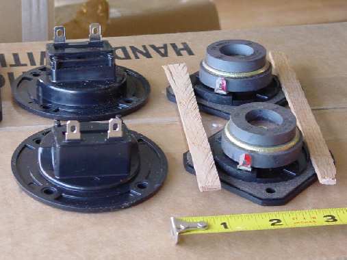
| After adequate time has elapsed for the glue to dry (cure) the machining starts. First establish the correct diameter holes for the woofer, tweeter and wiring cup. To measure this yourself, see Figure 6. Take two pieces of wood with straight sides across two pieces of the circular object you are measuring. Then simply measure the distance between the two sticks for an accurate diameter measurement. |
|||||||||||||||||||||||||||||||||||||||||||||||||||||||||||||||||||||||||||||||
| Figure 6. Measuring the speaker diameters. | |||||||||||||||||||||||||||||||||||||||||||||||||||||||||||||||||||||||||||||||
|
|||||||||||||||||||||||||||||||||||||||||||||||||||||||||||||||||||||||||||||||
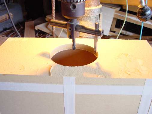
| The best tool for cutting smaller diameter holes of arbitrary diameter is a fly cutter, as shown in Figure 7. An Allen setscrew allows adjustment of the outside cutting spur. A fly cutter MUST be used in a drill press. Make sure to have a damp sponge or rag handy to cool the spur. I cut through the � inch MDF in four passes. After cutting for 10 seconds remove the bit from the hole and turn off the drill press. Press the sponge against the spur. Yeah, sizzle baby! This small precaution keeps the spur sharp and properly tempered. |
|||||||||||||||||||||||||||||||||||||||||||||||||||||||||||||||||||||||||||||||
| Figure 7. Cutting the woofer hole in the baffle. | |||||||||||||||||||||||||||||||||||||||||||||||||||||||||||||||||||||||||||||||
| Now it is time to route the recesses for the woofer and tweeter. This next step can be considered optional, but lends a professional look and better sonic quality to the speaker. A tweeter which is not flush mounted can have horrendous refraction problems. Routing can be done freehand our by using a guide bushing and a template. The woofer I used has rounded corners and the tweeter has truncated corners. The templates I made have square corners. This results in a rounded corner with a � inch radius. This will yield a bigger hole than required, but I figure a template routed hole which is slightly too big will look better than the irregular edges achieved by routing each hole by hand. Furthermore, I think the time to construct a 100% accurate template exceeds the cost of the components in this project. | |||||||||||||||||||||||||||||||||||||||||||||||||||||||||||||||||||||||||||||||
|
|||||||||||||||||||||||||||||||||||||||||||||||||||||||||||||||||||||||||||||||
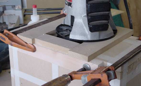
| I constructed the template out of � inch MDF scraps and some � inch pine scraps. First clamp the two pines strips to the side of the enclosure. I cut two scraps 4 1/8 inch wide to allow for the extra 1/8 inch from my guide bushing in the router. Then two other scraps are cut long enough to cross the baffle and the pine strips. The four pieces of � inch MDF are centered around the marked outline of the woofer. Then the four pieces of MDF are nailed to the pine strips. I used a pneumatic nail gun to drive 1 inch 18g brads through the MDF into the pine. This can be done by hand too. The finished template is shown in Figure 8. |
|||||||||||||||||||||||||||||||||||||||||||||||||||||||||||||||||||||||||||||||
| Figure 8. Router template assembled on baffle. | |||||||||||||||||||||||||||||||||||||||||||||||||||||||||||||||||||||||||||||||
|
|||||||||||||||||||||||||||||||||||||||||||||||||||||||||||||||||||||||||||||||
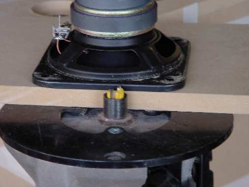
| Set the router bit�s depth placing a scrap which is the same thickness as the template on the router base. Place the speaker next to router bit and adjust the depth such that the speaker will be flush mounted. See Figure 9. |
|||||||||||||||||||||||||||||||||||||||||||||||||||||||||||||||||||||||||||||||
| Figure 9. Setting the router depth. | |||||||||||||||||||||||||||||||||||||||||||||||||||||||||||||||||||||||||||||||
|
|||||||||||||||||||||||||||||||||||||||||||||||||||||||||||||||||||||||||||||||
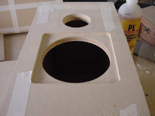
| Route the speaker recess by slowly running the router around the speaker circle until the bit is no longer cutting. Remove the router, turn it off, and set it aside. Before removing the template clamps verify that all the area underneath the speaker is planar. Also check the corners. Sometime sawdust builds up and prevents the bushing from following the edge of the template. The finished routed recess is shown in Figure 10. |
|||||||||||||||||||||||||||||||||||||||||||||||||||||||||||||||||||||||||||||||
| Figure 10. Baffle routed for woofer. | |||||||||||||||||||||||||||||||||||||||||||||||||||||||||||||||||||||||||||||||
| Initial Design and Box Assembly | Finishing and Final Assembly | ||||||||||||||||||||||||||||||||||||||||||||||||||||||||||||||||||||||||||||||
| Mechanical Drawings | |||||||||||||||||||||||||||||||||||||||||||||||||||||||||||||||||||||||||||||||
| Machining the Baffles | Making the SpeakerGrills | ||||||||||||||||||||||||||||||||||||||||||||||||||||||||||||||||||||||||||||||
| The Speaker Guy Home Page | |||||||||||||||||||||||||||||||||||||||||||||||||||||||||||||||||||||||||||||||
| Testing and Conclusions | |||||||||||||||||||||||||||||||||||||||||||||||||||||||||||||||||||||||||||||||
| Building the Crossover | |||||||||||||||||||||||||||||||||||||||||||||||||||||||||||||||||||||||||||||||