Dedicated to Really Cheap Audio Enthusiasts
The tweeter is the Parts Express model # 279-255, a Pioneer Mylar dome tweeter. This too is available at a bargain price of $2.95. It has a resonant frequency of 2.6kHz. Using a common rule of thumb says that with a first order crossover the frequency should be set at twice the resonant frequency, or 5.2kHz.
Unfortunately the optimum crossover for the tweeter overlaps the alleged dip in woofer�s response. Therefore I will choose a 2nd order crossover, set to 4.25kHz. I chose to use a Linkwitz-Reilly algorithm, well, just because. You could choose Butterworth or Bessel too.
I clicked on over to Steven Reid�s online Java calculators at:
http://www.globalnode.com/users/stevenr/spkrs/
Given the above criteria and the 8W impedance of my two speakers, the crossover calculator indicated I needed 2.34�F capacitors and 600�H inductors.
Here is where I went VERY unconventional: my component selection. Because this was such a cheap project I didn�t want to spend $30 on crossover components for a $5 speaker. So I used what I had access to.
The inductors are from Gowanda. They are 100�H each, toroid inductors with an iron powder core. They are good up to 100kHz, and have about 25mW of equivalent series resistance. They are rated for a DC saturation current of 2A. All in all, vary marginal, but I did have 24 pieces for free. I guess they�ll do. Each leg of the crossover used 6 of these in series.
The capacitors are unconventional too. I used Taiyo-Yuden ceramic multi-layer SMT capacitors. The only cheesy thing about them (for this application) is they are rated for only 25V. This is incredibly low compared to most crossover capacitors, but remember these are only 15W speakers. The reason most people use 250V caps is for linear performance, not because they need the breakdown performance. I used part # TMK316BJ474, which is a 25V, 1206 size, X7R dielectric 0.47�F capacitor with 20% tolerance. These are rated for about 500mA ripple current each and have an ESR in the low milliohm range. I used five in parallel on each leg of the crossover.
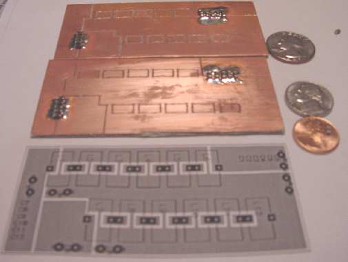
The crossover boards were made with single-sided FR4 with 2oz copper. I did a simple layout in my PCB software and printed it out in a 1x scale. The boards were made by first glue-sticking a copy of the layout on top of the copper, and then grinding out the isolation with a Dremel tool. The finished boards with the capacitors mounted are shown in Figure 11.
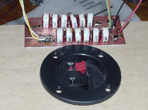
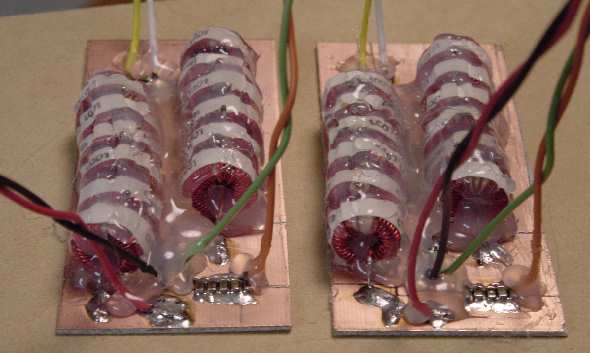
Next I used a hot glue gun to firmly fasten down the inductors to keep them from rattling. The completed crossover boards are shown in Figure 13, ready to install.