|
Ascot Roadster |
Body Development |
|
|
Computerized and rendered drawing of side view. A line drawing was developed from this concept. |
|
|
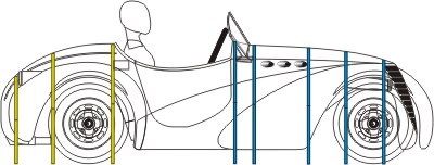
Line drawing developed from the rendered concept drawing. Yellow and Blue lines represent the plywood template locations (see below). |
The body of the Ascot Roadster is a GRP (Glass Reinforced Plastic or fiberglass) body. It is constructed of five pieces, the main body section, two doors, a hood piece and a trunk lid.
The design was first hand drawn on paper, with the chassis in strong consideration. The two designs were developed simultaneously. The paper design of the flat side view was then developed into a front, side, rear and top down engineering drawing. Once these drawings represented the desired shape, it was developed into a 3/4 front view and used for market testing reaction.
The line drawings were then light projected to full scale on a wall and traced on white roll paper. This allowed a more comfortable feel for the size of the car and proportions of the various elements, such as road height and door size. Several modification were made to the design at this stage, based on the marketing research and general "feel" for the concept.
The modified computer line drawings were then printed and used as small scale templates of the top and side views of the car. These were transferred to a urethane foam block and sanded to shape. This gave a scale model of the body and offers a chance to further evaluate the design and shape, in three dimensions. Modifications made to the 3D scale model body were then incorporated back into the computer engineering drawings. An important consideration is that having a scale model keeps the builders referenced to the desired outcome, while they are working on small sections. We have found this to be invaluable in building everything from Indy cars to shop trash cans.
Full scale templates were then printed out and used for the buck development.
|
|
Front View showing template "stacking" from front to rear. |
The templates were placed over a dimensioned light weight frame and located in place by welding tabs on the frame (see below). Flat areas of the templates are covered by flexible hard board and compound curves are made by inserting urethane form pieces between the curves and sanding to the templates.
|
|
Top view showing template "stacking" from front to rear. |
The entire buck, once shaped, will be covered by a thin layer of mat and fiberglass. The buck will then be worked to the final surface smoothness and will be ready for the mold making process. This is a critical and labor intensive step.
Body Buck Design and Production
The buck is made on a light weight frame, identical in the top surface to the actual chassis. Templates, defining cross sections are placed along the frame to define the outside body shape. The flat surfaces will be covered with hard board and the curved surfaces will be formed from urethane foam attached to the plywood templates. On completion of the basic buck structure, the entire buck will be covered with a thin layer of fiberglass mat and surfaced to the same level as the desired finished body pieces.
|
|
A urethane foam model was developed from computer printouts of the top and side views. This was developed to the point it was felt the design was mature. |
|
|
A scale model of the cross section templates was developed to check the location and shape. After this was proofed, the templates were used to develop full scale templates for the buck. |
|
|
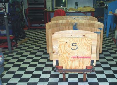
Front view of the buck in the early stages. The lightweight frame is held at the desired ride height by the frame legs seen at the front. The scale model stays close at hand and can be seen on the table in the rear. |
|
|
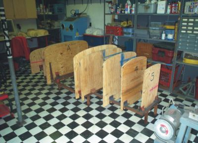
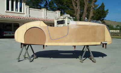
Side view of the buck in the very early stages of placing the plywood templates. |
|
|
Rear section showing the cross section templates as well as the vertical templates for the rear radius. Note the lightweight frame and attachment tabs for the plywood templates. A "round about" of 1/8 hardboard is used to check for template location confirmation and a smooth flow of all curved surfaces. |
|
|
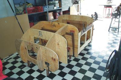
Further development of the buck armature showing access holes in all panels. This will allow internal access if necessary, after the outer skin is put in place. It also significantly lightens the buck, which will become increasingly heavy as it is developed. |
|
|
Side view of buck showing the nose template printout. The black area represents the grill. The flat engine section is actually the engine bay opening and the hood piece will be placed on top of this. |
|
|
First stages of filling between the plywood templates with foam. The foam has been sanded to shape, using the templates as guides. This will be be covered with fiberglass to add strength and provide a solid surface to develop the final shape and detail for the buck. |
|
|
Rear view showing foam at the early stages of forming. The top surfaces has been sanded down to the guide templates. The bottom area has not yet been developed and will continue to be sanded to the template and will be a rounded under, again following the developed templates. It's important to use one edge only of the templates for guidance. |
|
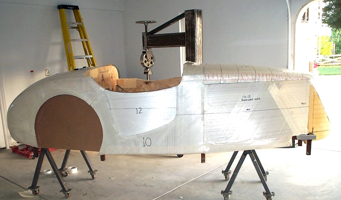
Later stage of foam shaping. The body is ready for a thin layer of fiberglass to be applied and then surfaced to a smooth finish. |
|
Body buck is now fully shaped and covered in fiberglass tape. Fenders are next to be constructed. |
|
|
Rear view of shaped body with may reference marks and notes. Note a printed out version of the dash has been attached. This allows a full scale feel for the overall size mated to the body. |
|
|
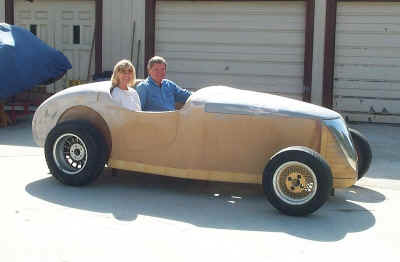
Overall size of buck at ride height. Wheels and tires are not sized correctly here. |
Home Concept Body Frame Chassis Steering Motor Trans Mount Dash Color Study