|
Ascot Roadster |
Chassis Design and Development |
|
|
Computer Chassis solid modeling of various components. Note the low mounting of the engine and location of the rear suspension members. Offset Watts linkage can be see in the top view. Rear axle is located by a 4 bar link system, of un-equal length and mounting angle. This system keeps the rear end pinion input shaft pointed at the transmission output shaft at all ride heights. This is necessary because of the very short coupling between the rear end and the transmission. |
|
|
Rear chassis frame location relative to the body structure. Modifications have been made to roll the body under the chassis, completely obstructing the view of the chassis from the rear. Ride height is approximately 5 inches. |
|
|
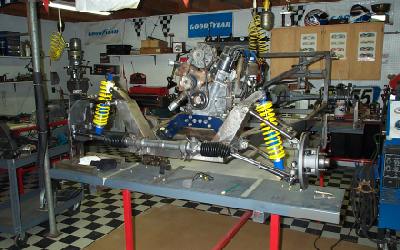
Front suspension design. Note that the upright mounting the shock and spring is below the height of the tire by several inches. Tire height is 22.5". This is a very compact design with substantial strength. Yellow block represents the outline of the engine and the blue member is the motor mount (see in next frame). |
|
|
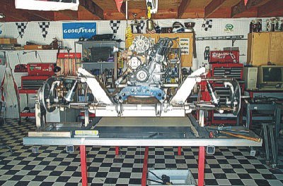
Chassis front view. Mounted on the surface table at ride height. Note single motor plate locating the narrow rotary engine well within the chassis rails. The front steer rack and pinion is located to eliminate bump steer but induce minor toe out in loaded roll. See suspension design criteria for reasoning. |
|
|
Side view of the left front. The left front is in full droop, showing less than 2 degrees total camber change. |
|
|
Right front suspension with the coil over shock disconnected. A fixture is holding the suspension at ride height. Visible are the commercial ball joints and small, lightweight spindle. The boxed chassis upright is fabricated and attached to a cross member in a jig. The entire unit then placed into the chassis and welded in the proper place. Anti-dive has been built into the upright in the jig. |
|
|
Close up of the mounting of the top ball joint. Ball joint is gold in color. Camber is adjusted by slots in the Aarm at the outer, top ball joint. Caster is adjusted by means of precision washers visible at the Aarm connection point on the chassis. Ground washers can be moved from one side to the other to achieve the proper caster. The same system is used on the bottom Aarm and results in a possible caster adjustment of over 10 degrees. This system is extremely simple, efficient and is not prone to going out of adjustment. Disk brake and dust cover are seen in the fore ground. |
|
|
Component parts of the top Aarm. The arms are made of seamless steel tube in a jig. Polyurethane bushings are used at the chassis pivot. Note the adjustment slots for Camber adjustment on the outboard end of the Aarm. Adjustment in excess of 6 degrees, positive or negative is possible. |
|
|
Bottom Aarm also utilizes polyurethane bushings for control. The arms are made of seamless steel tube in a jig. A commercial, small ball joint is used at the outer spindle contact point and is pressed into outer end. This is a typical GM mounting system and provides a solid, light weight unit. |
|
|
Chassis right front. Showing all suspension components removed. Note tabs on main frame rails, which locate the bottom Aarm. The mounting tube on the chassis upright can be seen and has been designed with anti-dive. The top mounting tabs on the upright hold the coil over shock upper eyelet. The blue motor mount can be seen in the rear. |
|
|
Rear end mounting, showing coil over shocks. Note the offset Watts link locating system running from the top left over the center section of the rear end. Ride height fixtures hold the rear end at proper ride height for prototyping purposes. |
|
|
Rear suspension is supported by coil over shocks, mounted to a chassis upright. The platform and threaded sleeve on the shock allow the spring to be adjusted by screwing the spring platform up or down. This is a typical adjustment method used on a racing chassis and works well on a small, lightweight car. The compact top, 4 bar link can be seen attaching to the frame. All of the rear suspension is maintained within the rear axle, forward. Disk brake calipers are not mounted at this point. |
|
|
Side view of the chassis with wheels in proper location. Tire height is 22.5" and the entire front suspension is below that height. Ground surface is located at the tire bottom. |
|
|
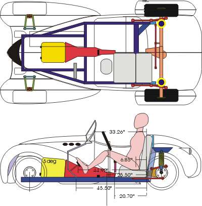
Side view of the chassis with a line drawing overlay showing the location of the body relative to the chassis. Note the low motor and suspension locations. |
Home Concept Body Frame Chassis Steering Motor Trans Mount Dash Color Study