 The Comfortable Pocket Yacht
|
|
|
Flicka Sailing
|
Topics
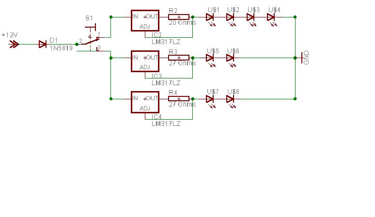
LED Cabin Lighting From the first time I saw a light emitting diode, I've been fascinated with their potential applications. Unfortunately, the technology of the period was not ready to meet my needs for usable lighting, low cost, and white color illumination. Starting in the late 1990s, white output LEDs were available at electronic specialty suppliers but at prices that made their implementation unrealistic. Furthermore, these devices were designed for spot lighting tasks with very narrow focused beams. Now, I'm happy to report that thanks to the needs of the automotive industry, wide beam high output LEDs are available in quantities and at prices that make home building of custom fixtures practical. Some LED fixtures originally designed for the recreational vehicle market are available and suitable for mounting in a boat cabin - however, I prefer to build my own. I may ultimately spend more building them myself - but having completed the exercise, I can maintain the fixtures and rebuild them if necessary. Boat electrical systems are tricky beasts, the short cuts that are used in automotive manufacture are really not suitable for marine use. As an example, marine systems may easily experience wide fluctuations in voltage as a deep cycle battery is first charged and then discharged. Automotive electrical systems are not subjected to this abuse. An LED system designed for automotive systems will operate well on 12.7 volts with a range of maybe five to seven percent. Marine systems are routinely stressed to a fifteen percent voltage fluctuation and often much more in the way of surge voltages. LEDs are specified by their manufacturer to produce a defined light output when driven by a maximum operating current. Under these operating conditions, they will require a voltage supply in a narrow range. Conventional wisdom is to string LEDs together in series and then use a current limiting resistor to bring the string of LEDs into their required operating conditions. This implementation is clean and simple - uses a minimum number of parts, and is easy to build. As an example, a common red LED available at Radio Shack is specified at 2 volts and 20 mA. The short cut builder will string 6 of these devices in series and call it good when connected to a 12 volt automotive battery Others will point out that a battery is really 12.7 volts and therefore a current limiting resistor is required (0.7 volts divided 0.02 Ampere = 35 ohms) - and the 33 ohm resistor from Radio Shack is close enough for government work. Unfortunately, the manufacture's fine print is not part of the Radio Shack package. While the device is nominally rated to draw 20 mA at 2 volts, the range can be from 1.7 to 2.4 volts for 20 mA. Depending on the batch of LEDs in stock, the short cut builders may have much less than full light output or worse yet, they will blow the devices out as soon as they hook up their battery charger and the power supply rises to near 14 volts. One solution to this dilemma is to install an active voltage regulator in the circuit to eliminate this issue of changing battery voltage. While a good solution, it does not address the issue of getting the most light out since each set of LEDs may require a separate voltage setting for optimal output . The solution I recommend is to create a constant current source. Constant current sources are even simpler to create than a constant voltage source. A routinely available LM317 voltage regulator and a single resistor are all the components that are required. The current source is adjusted by varying the value of the single resistor. To determine the value of the resistor required, divide 1.25 by the required current in amperes so for 25 mA, 1.25 divided by 0.025 is 50 ohms. For the 20 mA source in the example above, all that is required is a 62.5 ohm resistor. Since this value is somewhat hard to get, two common 33 ohm resistors in series will substitute nicely and yield an output current of 18.9 mA. A voltage regulator like the LM317 requires a minimum difference between the input and output of close to 2 volts. Also, other components in the design such as blocking diodes will drop the input voltage somewhat. When designing LED arrays, I prefer to be on the conservative side and use fewer units in series to make sure that the regulators function as designed. One more caution in the fine print. The typical LM317 regulator I'll be using requires a minimum current flow in order to operate correctly. Generally, this is on the order of 10 mA but some devices are available with specified minimum currents as low as 5 mA. Onward To The Design - The Circuit My goal was to build a series of devices that could contain single color LEDs or combinations of LED colors such as white and red (for night vision retention). The circuit should be designed for reliability and conservative component ratings. I also wanted to make sure that the circuit would operate over a wide range of input voltages. I had already decided to use the new ultrabright 4 pin LEDs so that much was certain. These devices operate on relatively high current and have a broader than typical voltage variability in their manufacture - but they are perfect for current control. While I wanted to use the nominal 12 volts offered by a deep cycle Lead/Acid storage battery, I did not want to rule out other sources of power. Nor did I want to ignore the voltage spikes that can occur on a sailboat. Since size was important, I also wanted to get all components into the smallest space possible. My final circuit employs an LM317LZ voltage regulator configured with a single 1/2 watt resistor to form a precision current regulator. The final schematic is shown below as configured to support a bank of 4 Red LEDs and 4 White LEDs. The switch in use is a center off SPDT type (click on the image for an enlarged view).
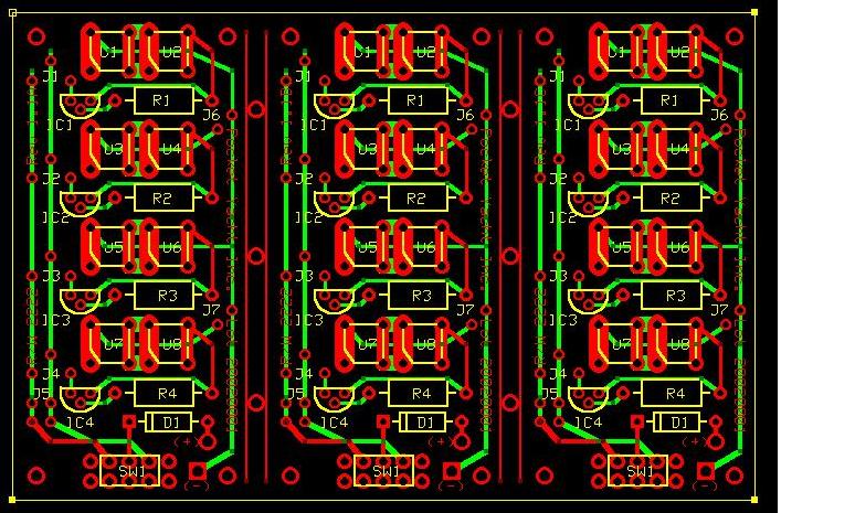
This schematic only shows one possible configuration of the LED board. Other layouts allow for all 8 to be the same color. Another configuration allows for 4 Red LEDs and 4 Yellow LEDs. In each case, the bank of LEDs consists of one resistor and one LM317LZ regulator to provide the current regulator functionality. Onward To The Design - The Printed Circuit Board I had tried to make my own printed circuit boards in the past with dismal results. While making these at home is clearly possible, I would waste considerable time, effort, and money in setting up the necessary equipment. Just considering the accuracy of drilling the holes in a PC board would make me shiver - and the boards I was considering would have about 300 holes in an area of 2.5 X 3.8 inches. My conclusion was to use a custom board manufacturer and I turned to ExpressPCB for the task. They offer a complete web based solution to custom printed circuit boards. Layout software is downloaded at no cost from the Internet and the finished layout file is uploaded to their server for manufacture. A few days later, your custom boards are delivered to your door ready for incorporation into a project. ExpressPCB offers a mini-board service that was ideal for my needs - it's a one size project - all you can cram onto a two sided board 2.5 by 3.8 inches. For a single price, they manufacture three boards to your specifications and deliver them to your door via second day air service. Fortunately, I was able to design the layout so that one board could support three sets of 8 LEDs - in fact, I could either cut the board into thirds or use it intact. I also loaded the design with jumper wires so that the board could support several different layouts and optional configurations of up to two colors. The image below shows the prototype layout. Red depicts the top copper layer, Green is the bottom copper layer, and yellow represents the component outline (click on the image for an enlarged view).
Onward To The Design - The Parts List While there are a number of catalog suppliers of electronic components, I will provide the part numbers from Newark Electronics for reference. Those that want to duplicate my efforts can substitute parts and suppliers at will.
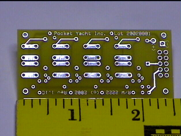
* Local supplier - these components are best obtained locally - substitutions are freely made here depending on what is available- as an example, if you can't source a 20 ohm resistor locally, Radio Shack sells 10 ohm resistors and two in series will substitute. The photo below shows a completed circuit board in it's bare form (click on the photo for an enlarged view).
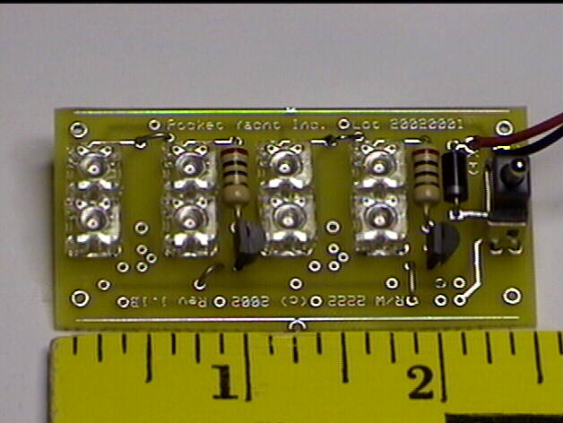
The photo below shows a completed circuit board populated with 8 LEDs in two colors designed as 2 banks of 4 units. The switch on the extreme right selects Red/Off/Yellow in this case (click on the photo for an enlarged view).
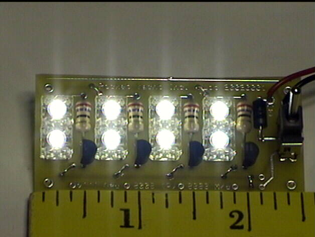
The photo below shows a completed circuit board in the "On" state populated with 8 white LEDs. In this configuration, the board draws 180 milliamps (click on the photo for an enlarged view).
Under Construction - I'm still working on the enclosure - stay tuned - I'll post it here when it's finished. This page was last updated on September 02, 2002 08:45 PM |
|
Copyright © 1999-2002 Jobst Vandrey |