 The Comfortable Pocket Yacht
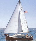
|
|
|
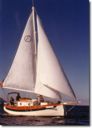
Flicka Sailing
|
Topics The Refit of Solar Wind No boat is ever exactly like the new owner wants. There are always changes to be made and often those changes involve redoing things that the previous owner had spent a lot of time on but no longer suited the purpose of the new owner. I am no exception – I’ll want things my way – despite the good experiences, invested time, energy, and money of the two previous owners.
The existing panel was approximately 30 watts and would not meet my energy needs. Tests I ran showed it’s output to be less than expected but this was corrected when I found a bad connection in the wiring harness and also removed the blocking diode that was really not needed in this electrical arrangement. This brought the panel up to about a 1.2 amp output in full sun. Combined with the parallel output of about 1.8 amps from my 40 watt Kyocera panel, I expected to eventually become independent of any need for shore based power sources once I brought the group 8D gel cell battery up to full charge. The two solar panels were routed in parallel to a Morningstar charge controller set to the care and feeding parameters for a gel type sealed battery. The existing 30 watt Solar Panel was mounted on the top rail of the pushpit Not a bad location but that meant that the traveler had to be disabled and the mainsheet control mounted on the middle rail of the pushpit. Again, this was not the best arrangement. Adding a second panel to the pushpit would make things WAY too crowded so an alternate location needed to be found where both solar panels could be mounted out of harm’s way and yet in the full sunshine. While I saw no perfect solution, I decided to start by mounting the panels on the bimini. This does make impossible to lower the bimini without a great deal of effort, shifting around, use of tools, and foul language. However, I feel that this is a small price to pay for the benefit of two solar panels creating all the electrical energy I need from mother nature’s free sunshine.
My plan was to use this compartment only for storage of dry food and other necessary supplies. I really did not want to use any refrigeration – or at least, I’d try to start out that way. Unfortunately, Solar Wind’s ice chest had been modified to add insulation made from a double layer of thin foil and plastic bubble wrap. This material had been attached to the inside of the ice chest with some type of spray on adhesive. The seams had been covered with duct tape and then coated liberally with silicone caulking. The ice box drain had even been plugged up with some type of filler. While nice in theory, the condensation, standing water, and rough interior surface made for a mold’s idea of heaven and was black with unidentified imbedded growth. This all had to go – and NOW! It took two days of scraping and a full bottle of Goo Gone before I saw most of the interior back in some sort of usable condition. There are still some areas of foil that are solidly embedded to the surface but at least the interior of the ice chest is once again dry and relatively clean.
Solar Wind’s 20 gallon water tank was plumbed to the sink using an in-line electrical booster pump. From the specifications, the pump was capable of pumping better than two and a half gallons of my limited fresh water supply per minute while using 2.6 amps of my equally precious 12 volt electricity. This waste of resources (both fresh water and electricity) would never do for cruising. However, it was very convenient for now since I could use the system to clean out the tank by running several cycles of fill and empty using fresh water from shore sources supplemented with a cup of bleach. I would have to get back to this water project at a later date when I started to integrate the PUR Survivor 35 into the system. For now, it was enough to completely disassemble and clean the hand pump, replace all the old tubing, and sideline the electric pump. A rebuild kit was purchased from West Marine and the hand pump brought back from a totally inoperable frozen lump of brass to a functional piece of equipment. If I had a choice, I would have installed a foot pump, but this arrangement for fresh water would do for now. I may however use the in-line pump supplemented with a strainer to provide salt water to the sink at a future date. This would be possible since I have an unused raw water thru-hull fitting that was originally designed to supply water to the marine head. Unfortunately, this sea water idea will have to wait till the next haul out since I discovered that the DPO (dreaded previous owner) had filled the tail of the seacock with silicone or some similar material. During the survey, this was not discovered since there was a cap on the tailpiece that was not removed. I will need to do some major surgery here in order to make this a useful setup. Lesson Learned – ALWAYS check All the Thru Hulls when the boat is hauled.
Most of the teak had been left untreated and may have had a coat or two of teak oil at one point. Only the upper part of the cabin teak had been varnished previously and that was not in the best condition. This varnish had started to deteriorate and would need to be stripped back to bare wood. The untreated teak around the companionway hatch and the door to the head was in the worst condition and needed more than a just a light sanding. My intention was to get all surfaces back to some reasonable bare condition and then use multiple coats of a tung oil preparation to seal the teak and eventually give the interior a hand rubbed appearance. For now, my goal was to apply enough of an oil finish to protect the teak and prevent further deterioration. For the varnish removal, I chose to use a chemical stripper compound. While there are many on the market, I ran across some Citristrip in a gel formulation that sounded like it would be ideal. This product did not contain methylene chloride and might be easier to use on the vertical surfaces in the cramped cabin interior. In fact it worked quite well and I was able to get the varnish off with only one day’s effort. The worst areas of darkened wood were then given a light sanding and treated with a 50% bleach mixture and left to dry for 24 hours. Then all wood surfaces were treated with Dalys SeaFin Teak Oil. This is a Tung Oil mixture that had been highly recommended for getting a hand rubbed look on the interior in a book on refinishing marine brightwork. This operation was very time consuming since 4 coats are required at 8 to 24 hour intervals. All things said and done, I am happy with the look! Eventually, I will go over the surface again with more coats and wet sanding between coats. This project will need to wait till I can completely strip the interior of everything that is not nailed down. This type of an extensive refinish operation is not really possible to do while I am also living on the boat.
The only thing that really need to be seen to in this department was the depth finder. I needed to determine where the transducer was located and calibrate it either relative to the water surface or to the bottom of the keel with appropriate offsets so that I could be sure of the readings. It ended up that the transducer was located port side and about 1 foot three inches below the normal water line next to the cockpit drain thru hulls. To be conservative, I programmed the display with a one foot offset so that the system now reads actual depth of the water column on the port side of the keel with a three inch positive margin of error. Murphy took this recalibration to heart and presented me with an opportunity to verify the setting the same night when the lowest spring tide of a new moon caused Solar Wind to rest her keel on the bottom for 45 minutes or so while tied to her slip. The instruments (Depth and GPS) were already mounted on swing out arms so that they could be conveniently read from the cockpit. The compass was mounted on a bracket to the exterior of the companionway and was returned to a storage location when not needed. Fortunately, the US Military took this opportunity to turn off selective availability on the GPS signal so the readings would now be much more accurate. Maybe even accurate enough so that speed over ground measurements from the GPS would even be meaningful in adjusting sail trim!
No discussion of Florida and refits would be complete without mention of the need for bug screens. The boat had been equipped with a companionway screen already but no screens were installed on the opening hatch forward or any of the six opening ports. My attempts to create screens for the ports have so far been futile but the directions for creating a hatch screen in The Sailors Sketchbook worked like a champ. The only modification was to use sticky back velcro and attach the hook side to the headliner around the hatch. Then the sticky back loop side attached in several places around the edge. After an oversized section of screen was held up to the hatch, the sticky back adhesive held the fiberglass screen in place while I added a thick layer of clear silicone caulk across the back surface of the screen. This was smoothed with a wet finger and the result was to embed the fiberglass between silicone and the velcro backing.
Quite honestly, I had been hoping to save any significant electrical work for a later time. Unfortunately, Solar Wind’s steaming light had bee removed by a previous owner and this was a requirement for me since motoring after dark would be a likely event in the near future. The deck fixture was still in place for the steaming light but when I looked at the cap, I found that the interior of the fixture had been filled with some sort of stone hard putty. I ended up drilling out the filler and found that it extended all the way thru the deck to the inside of the boat. Inside, the situation was just as bad since the wires had been cut short at the mast step and again at the electrical panel forcing me to splice in extenders. After 6 hours of effort and several trips to West Marine, I had a functioning deck fitting again. Since I had no intention of climbing the mast to install the steaming light at it’s normal position above the spreader, I drilled some holes as high as I could reach up the mast and installed the light there. This should meet the requirements since the rules just call for this light to be mounted one meter above any other light that would be on at the same time (side lights and stern light). I ran the wires down inside the mast and fished them out thru the hole already there in the side of the mast where they connected to the deck plug. In anticipation of eventually adding an anchor light at the masthead again, I installed a 4 pin deck fixture. I did review the switch panel for other obvious things to correct, but outside of several bad connections that could be fixed easily, I left the rest of the panel as a project for another day. This page was last updated: 09/14/00 05:08:10 PM |
|
Copyright © 1999-2002 Jobst Vandrey |