Grades can make or break a layout. Sooner or later they become a necessary evil for bridges and level changes or just a trestle set. It is a good idea to find out how they will effect operation before any are added. EQUIPMENT WEIGHT is a big factor in limiting grades, while even curves effect them.
See PHYSICS for a discussion of the terms used.
For practical purposes the gradient is usually taken as the ratio of the rise to the run length at railhead level. Although occasionally listed as feet rise per mile, both prototype and models measure gradients in percentages. Measuring in angles would require a very accurate divider or transit, since a steep 7% gradient = about 4 º and the difference between a 1% and 1.5% grade is only about .2865 º. For those familiar with trigonometry; to a close approximation for small angles, the ratio = sine g = tangent g = g in radians. At 7% gradient, the error is less than .3%. Even on a run measured with a 50" level, the difference in the rise between using the slope and horizontal distance is only .0085". Normally horizontal distance will be used for layout planning and slope for construction.
To estimate the gradient ratio G, divide the measured vertical difference by the measured horizontal or slope distance. Short angle levels are not accurate enough for grade use. The best way to layout a grade is by using a good quality, MODIFIED BUBBLE LEVEL _ with a locking screw adjustment for height. The height may be measured with calipers or for a more exotic approach, fit the screw with a calibrated wheel. To make calculation simpler choose a length of 24" or 48" to start and extend the screw attachment to 25" or 50" so that the grade ratio can be divided by 4 or 2 for screw height. For open benchwork, sub=roadbed should be supported on cleats at tops of risers. While building grade, risers are temporarily clamped to joists to permit adjustments. Once finalized they are screwed together. Unless you like surprises, do not use nails.
Even though angles are very small, vertical easements are necessary at all grade changes to reduce wheel lift on long rigid wheel bases and collisions at tops of long cars. A long strip of flexible sub-roadbed, extended and supported along tangents on either side of intersection, but not supported in the middle section; will form a natural easement. The unsupported curve length should be longer than the longest equipment. Homasote does an excellent job. Avoid breaks in roadbed or track near the intersection. Slightly pre-curving track vertically may be necessary on larger changes.
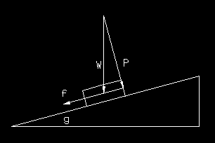
The weight of cars and locos interacting with the gradient determine how well the train climbs the slope. For cars there is a net force downward parallel to the slope representing the slope drag force (f).
NOTE: Level drag of cars or locos will not be included in the first part of discussion , since the weight on bearings and the friction produced should remain virtually constant.

Forces for car on slope.
The triangle with vectors is similar to the slope triangle, so angle g is equal to the vertex at the top of and all ratios of respective sides are equal. As a result of the weight W, the drag force f down the slope is:
f = W * sin g = W * (rise / run) = W * gradient ratio G
For a three ounce car on a 2% grade:
f = W * G = 3 * .02 = .06 oz
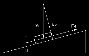
Since tractive effort is another factor, locos are a little more involved. The force f is computed the same way, but the total weight includes the loco plus tender or dummies. For the tractive force Fs, only the weight on the drivers is considered. First the coefficient of friction C must be found on a level track. The actual values is derived from the surface molecular characteristics and reaction between the driver tires and the railhead. In prototype usage the ideal factor of adhesion A is the reciprocal of the coefficient of friction. Commonly values are around A = 4 and C = 1/4 = .25, while in models the value is usually less than .2 or A is greater than 5. Very often the prototype tractive effort is computed from standard formulae.
C = drawbar pull / weight on drivers = Fs / Wd

Forces for loco on slope.
On a slope Wv is the vector force and direction of Wd against the rails.
Fs = Wv * C = Wd * cos g * C
where g ° = arcsin G
Since C is a constant on the slope, Fs can be found directly from Fs on a level from MEASURING DRAWBAR PULL :
Fs = Fl level * arcos g
For a typical HO loco on a gradient of 4%, a Mantua all metal Pacific weighs about 21.25 oz with a weight on drivers of about 20 oz and tender weight of about 10.75 oz for a total weight of 32 oz. The level drawbarpull is about 3.5 oz.
C = Fl / Wd = 3.5 / 20 = .175
g ° = arcsin .04 = 2.29 °
Fs = Fl * cos 2.29 ° = 3.497 oz.
The net tractive force Fn is the difference between the up and down slope forces. f is determined from the total weight = 32 oz.
Fn = Fs - f
Fn = 3.497 - 32 * .04 = 3.497 - 1.28 = 2.217 oz
About 37% of the tractive effort goes to lifting the loco and tender up the slope. Heavy tenders or dummies make a wasted difference.
To determine the number of cars that can be handled, first the sum of loco drag force f and the horizontal drag per car must be found. According to one test in HO, Fh of one ounce equals 14.5 "standard" 6 inch cars at about 4 oz each. Each car requires about .069 oz pull.
Fc = .069 + .04 * 4 = .229 oz
By dividing this into the net loco drawbar pull, the number of cars N can be found.
N = Fn / Fc = 2.217 / .229 = 9.68 cars.
This is a theoretical maximum which may be reduced by additional friction from curves, wheel bearings, improper lubrication or other sources. highly touted device for measuring grade effects for hump yards, car rolling quality and tractive effort. To be effective it must have very accurate measurements including a well calibrated vertical adjustment device and careful leveling. Crude but effective comparisons can be made by mounting a length of track with a rubber band stop, on a rigid base and placing blocks under the other end. Light tapping on base should be used to overcome static friction, rather than inconsistent pushing.
To calculate drawbar pull the first equation above is used:
f = W * sin g = W * (rise / run) = W * gradient ratio G
While a loco is climbing an increasing grade, the drivers will start to slip when the tractive effort equals the downhill force (f) of the total weight including tender, dummies etc. At this point the tractive effort is simply the weight times the grade. If the grade is 11%:
f = W * gradient ratio G = 32 oz * .11 = 3.52 oz
To be effective, one end should be adjustable by a calibrated screw dial, similar to a vertical feed and the base must be level. With a stationary loco on track, raise slope until downhill slipping occurs. Reduce slope and run loco uphill and adjust until slippage just occurs. Average several readings.
BACK TO LINES & LEVELS
BACK TO MEASURING INDEX
BACK TO SQUARES, BEVELS & MITERS
BACK TO TIPS ON TESTING
BACK TO WEIGHT
