Mounting or remounting couplers are very often necessary evils. The process sometimes can be very complicated, but an understanding of the operation requirements and the right approach can reduce the stress.
NOTE: For the sake of good operation, hornhook (X2F) couplers should not be used. Due to off center springing, side thrusts tend to push wheel flanges into rail joints and turnout points, causing potential derailments. This is augmented by talgo mounts during pushing, resulting from increased leverage in pivotting truck. Body mounting reduces thrusts, permitting flange contour functions to guide wheels.
COUPLER OPERATION
Assuming that magnetic knuckle couplers. with delayed action, will be used, some consideration of their function is in order. Viewing the coupler head from the top it resembles an open right hand, in the medial position, with fingers curled and thumb extended to side with a gap. The rigid finger knuckles are equivalent to the knuckle, while The finger-hand knuckles repesent the knuckle hinge.
Knuckles are kept closed, during movement, by various spring concoctions. These may be a metal coil or a plastic leaf on the head at the hinge or with no hinge as in the Kadee 711 and the Accumate,with metal coils inserted into the scissors shanks inside the box. Although some rumors claim fatigue problems in the plastic leaves, basically there is no difference in performance. In contrast to the prototype "s" shaped pulling face with a bulbous tip contour and less than 3/8" slack, most model couplers have flattened faces with large clearances between faces and crooks. Thumbs have wider gaps to increase gathering and to permit tips to pass during coupling. To compensate for this, raised rims are added at the pulling face tips to reduce potential separation during pulling.
During prototype coupling, knuckles are opened completely, exposing the crooks, by lifting cammed pins via the cut levers. Carefully aligned, they bypass each other and their tips push against integrated levers in the crook, on the opposite side of the hinges. This forces the knuckles to close and pernits the pins to drop, locking the knuckles closed. When opened during uncoupling, they will remain open uless disturbed. The last HO couplers to operate this way were MDC and Devor, which used a ramp to lift "hose" pins to open. As with the prototype, if knuckles were accidently closed, coupling was impossible.
To eliminate the problem on models, the closing springs keep knuckles closed all the time. But they permit contoured ends to force knuckles open, when pushed together during coupling, then close them after tips pass each other. Thumbs are angled outward to help aim tip sand permit them to pass. The slant also helps to close knuckles as the end corner approaches the crook. It is not unknown for the thumb tip to dislodge spring on sharp curves.
Due to the security rims, to uncouple, couplers must be pushed together over the magnet, forcing knuckes outward. The tips may not clear in the fully pushed position; but as separation increases, by magnetic force, the corners ride along the thumb slant and permit the knuckles to open sufficiently to pass. On occasion car momentum and a balky locomotive can bunch up couplers over a magnet and produce uncoupling by duplicating this action. This is a good reason not to place magnets on running tracks.
Delayed action is accomplished by completing the uncoupling separation until the head end clears the thumbs. At this point, the heads should swing out until the knuckles clear each other and only the thumbs are aimed toward the crook. Pushing together will seat the thumbs in the crook, thus pushing the car. Once car is spotted, couplers are separated and return to center. After leaving magnet, care must be exercised that erratic movements do not permit thumbs to exit crook, thus permitting heads to center and couple.
Various centering springs are required to align heads during coupling. With their #5 type shanks, Kadee uses two different force, metal leaves mounted on a thin plate to accomodate the lesser delayed action swing. Their very high, 30 (intermediate 6,7 & 8) series uses two different hair springs for the same purpose. Whlie their original 6, 7 & 8 operated well with only one hair spring. The pesent, very wide, 6, 7 & 8 uses a grotesque side extension lever with a longtudinal shank spring. While the #4 performs well with the same springing and no differenciation. The Kadee 711 uses the same type spring arrangement, but with a rigid knuckle and two part scissors action and possible differenciation using shank pinss. With scissors action, Accumate uses two different cast-on curved flat wire types. Intermountain, McHenry KS and Bachmann II use similar cast-on wires with no apparent differenciation. During tests only the plastic leaf knuckle spring type McHenry exhibited minor problems with delayed action.
In addition to springing, basic problems exist in that end contours, rim sizes, knuckle hinge to tip lengths, thumb gaps and slack vary considerably.
This is where the "fun" comes in. Even though in the 50's, the NMRA attempted to standardize draft gear and mounting; almost every manufacturer seems to have his own idea on how to screw up the works. In Ho the first digression from the recommended box, was Athearn's introduction of Globe's ring shank. KaDee met the challenge with the 5&10 shanks. But due to the introduction of cheap and lousy horn hooks with their lopsided springing, newer developed boxes varied drastically with internal projections almost anywhere. With the introduction of truck mounted couplers, things grew worse. It seems as though most designers are driven to re-invent the wheel by varying every dimension possible. Standards and Recommended Practices are sorely needed.
Before any mounting decision can be made, an examination of car or loco characteristics should be made. Mounting possibilities and curve compatability must be evaluated. During the process, some cosideration should be given to CLOSE COUPLING to drastically improve appearance. Although this usually requires more work, the results are rewarding. Many articles have covered various aspects of problem mounting. Some ideas are presented below. On their site, Kadee presents a list of conversions , that is not always current, not fully inclusive nor the best; but may prove useful for ideas.
Before selecting couplers, car heights should be checked at floor level and corrected, if necessary. Due to station platform requirements, this is a standard for passenger cars at 3' 7 1/2". Freight cars vary with type and use. House cars run from about 3' 7 3/4 " to 3' 9 5/8" and . Floor to roof height may vary on models of same car. The actual floor level may not be obvious, but usually a line of support rivets runs about an inch or so below it. Flat cars run from 3' 5' to 3' 9 5/8. Each car and type should be checked against car diagrams, if possible.Final setting should be at ends of cars, where they are judged. See MEASURING ROLLINGSTOCK HEIGHTS.
After setting floor level, the mounting surface or pad height must be determined in order to select shank to knuckle offset and box inversion sense. For both cast on or separate, body mounted boxes; shims or removing material by filing may be necessary to adjust height.
Next search for a coupler that may fit with minimum effort, but still provide the desired operation and spacing. Since not all couplers are created equal, selection of the right coupler, make, style and measurements can be a strong influence on decisions. Most dimensions vary considerably. Especially with cast-on types, boxes vary in every dimension, creating chaos. In spite of hype, drop-in couplers are not totally compatable in almost all boxes, including their own, even to the extent of effecting operation. Sagging knuckles and excessive play are common. Centering and delayed action often suffer. Although they should be uneccessary, corrections can be made.
For a better understanding of coupler dimensions and their relationships to boxes, Some critical comparisons are shown in MEASURING COUPLERS.
Although it may appear burdensome, a little extra attention goes a long way. To achieve best operation, all couplers should be cleaned up by removing flash and push pin scars. Box and lid front edges should be lightly beveled to eliminate any possible snags.. The back edges of a #11 blade make excellent scrapers without gouging. A final burnishing of all contact surfaces, with graphite, greatly improves movement.
MOUNTING
 Caution: Contrary to
popular advice, preferably, boxes and lids should not be cemented.
In the event of damage, failure or later adjustment; disassembly could
be required and undoing cement joints often tears things up. Many of
the snap-in pins break during lid removal and often do not align shanks
properly. Since on Con-Cor's 60' parts or express cars, the extended draft
gear does not clamp tightly, permitting coupler sag, adding screws can
eliminate the problem. By cutting off pin and using scar as a center guide,
a screw clearance hole can be drilled in lid. In plastic short, flat or pan
head screws will tap themselves into the pivot hole. If drilling for larger
screw, stop just before punch through. In most cases 1/8" length screws are
sufficient to secure lids. Slight countersinking will recess flat heads.
Caution: Contrary to
popular advice, preferably, boxes and lids should not be cemented.
In the event of damage, failure or later adjustment; disassembly could
be required and undoing cement joints often tears things up. Many of
the snap-in pins break during lid removal and often do not align shanks
properly. Since on Con-Cor's 60' parts or express cars, the extended draft
gear does not clamp tightly, permitting coupler sag, adding screws can
eliminate the problem. By cutting off pin and using scar as a center guide,
a screw clearance hole can be drilled in lid. In plastic short, flat or pan
head screws will tap themselves into the pivot hole. If drilling for larger
screw, stop just before punch through. In most cases 1/8" length screws are
sufficient to secure lids. Slight countersinking will recess flat heads.
Almost a necessity, is a CRADLE to hold model during all phases of mounting; unless you have three hands.
Shims should be added to eliminate sags. "Hoses" on magnetics should be tested for clearance of ramps. Finally to check operation; a cursory hand, test track, trial and adjustment is in order. Hoses are more easily adjusted with jeweler 's pliers having one convex and one concave jaw which provides three contact points to adjust curvature. Proper mounting of uncoupling devices should not be overlooked. The Kadee double sided jig rests on rail heads and has a steel center which holds magnet at the correct height while gluing to ties.
Determined by case, there are several method used; but all have some basic requirements. Including pad heights, centering pin diameters, box lengths, heights and widths; shank styles, thicknesses and lengths; to list a few. Even with built-in boxes, many of the variations exist. Thus begins the real challenge with the often frustrating guessing game.
If cast-on boxes are present, they should be measured and checked for compatability with desired coupler.
Shims can be made from Evergreen strips or trimmed down, excess coupler boxes or lids; using the proposed box as a template for sizing.
Since designers have not yet agreed on mounting pad and cast-on box dimensions, body mounting draft gear is an art, which may require considerable forethought and trial.
With knuckle heights as low as .126, extra care is critical to avoid over ride at grade change intersections. Measure boxes carefully, since most manufacturers list nominal or rounded off values. If a large number of mountings are done, setting up a data base can help rapid selection. Mine has 101 coupler shank and box mounting combinations, each with 27 indexed, dimensional data, calculation and virtual cells.
Knuckle center heights should be very carefully adjusted with a gauge to prevent unexpected uncoupling at grade intersections.
Probably at this stage the best aid is the box itself. Test for fit in the proposed location, to ensure clearance of underframe obstructions and to permit truck and coupler swing on tight curves. Some boxes may be trimmed without effecting operation. Commonly on brass cars air hoses and piping interfere with mounting. Some cases require relocation of pipes or trimming them to obtain a flat mounting pad. Before any surgery, examine alternative boxes such as the universal adapter plate included in Kadee's 20 series. Most tenders fit in the car category, but due to foot boards, they may require longer shanks. For more details, see the technical discussions on COUPLERS and CURVES AND COUPLER EFFECTS. The aids needed can be determined, once a decision is made.
NOTE: The alignment lips on top front of some boxes are not sacred for determining pivot center and in many cases, are superfluous and can be removed. For more realistic CLOSER COUPLING, often knuckle rears or pulling faces are used as references with shorter shanks or greater center set back. Other than cosmetics, the only requirements are that the knuckle clears all parts on the end sills throughout its swing, the swing is enough and corner posts clear on sharpest radius.
To convert older cast on boxes with square #4 type center posts to different shank lengths, several choices exist. Where the lid is screwed on, press a Bowser or Kadee bushing over post and install the selected ring shank coupler as usual. In cases where the pivot location must be changed or the lid is not screwed, the post is removed and a screw hole is drilled and tapped in box at the desired location. An excess #5 lid with post is then trimmed down to fit box. Since assembly is inverted; to ensure the centering spring is on the post, assemble on lid with spring on top of the shank and clamp with tweezers to hold until securely screwed in place. Removal of end lip makes clamping and the use of the 703 jig easier.
For accuracy in locating separate boxes, two center lines must be established to locate pivot point. First the set back, determined by the desired reference to pivot distance is marked clear across the body perpendicular to sides. Next two arcs, with a radius slightly larger than half the width and centers at the intersection of the set back and sides, are drawn using a compass. The longitudinal center line is drawn through the intersections. Drill at the center line intersection for center screws. For side screw mounting, a circle is drawn with a radius equal to half the distance between box mounting holes. Metal templates have been offered in the past for KaDee 4 , 5 and NMRA boxes, but with all the diversification of boxes today, they are of very little use.

Note: Adjust brightness and contrast for optimum viewing.
Establishing center lines for screw locations.
Assembly is mounted with estimated shims and work is checked on track with a height GAUGE. Adjust accordingly. Shims may be cemented to top of box or floor to prevent drop out on disassembly. Here the tweezers are almost indispensable.
There are many situations that require special attention. On locos and older cars with metal frames, often the coupler pads are hot, requiring insulation to prevent incandescent coupler springs. The usual practice was to orient trucks with hot wheels on the same side to eliminate shorts through them; but this did not eliminated shorts though couplers, when two cars with opposite polarity frames were coupled. The newer acetal plastic couplers help relieve these problems.
Loco pilots present the most problems and they seem to increase with price. Often in the zeal to create close to scale realism, coupler pads and mounting space are neglected. In N scale, often the entire pilot had to be replaced with an adapted one. In other scales, very few adapters have been developed, leaving the rest to imagination. Although most tender couplers are isolated permitting short-less double heading, there is always the possibility that two hot pilot locos may be coupled nose to nose. Couplers should be insulated , if at all possible. Usually slightly antiquated, for years Kadee has provided a list of conversions for many applications. But beware, they are not all the best methods. Chopping through prized loco pilots is not appealing. Very careful analysis is required to preserve the detail and achieve good operation.
If present, truck clearance must be considered first. Determine the swing on the minimum radius used, since no draft gear may fit without interference. Often axles or wheels are too close for comfort. Particularly on brass and especially passenger steam locos, pocket openings do not even pass shank centering rings, let alone boxes. Assembly in place may be required, if possible. On larger, steam, road loco pilots; delayed action may not be necessary for the less stringent double-heading requirements. This may alleviate some of the strain.
Without coupler, try selected box for fit, observing obstructions and truck clearance. Check shank length and style plus access through coupler pocket casting. The "hose" and knuckle rear must clear all pilot detail. If none exists, determine possible mounting hole locations. Usually boxes may be trimmed without reducing effectiveness.
Although a #4 type shank will pass though almost all pocket openings, length may be too short. Insulation and mounting are also problems. A pin-less , plastic box may be used with a nylon pivot screw to insulate,
Older K and MK series, .250" OD, draft gear can eliminate pilot surgery and provide delayed action, as in this circa 1966 conversion. In spite of suggestions, they were dropped from the line. Since possibly, the dies still exist; maybe Kadee might be induced to produce these again with acetal washers, instead of fiber. The fiber washers are still offered, while apparently only one hair-spring is used on the 30 (first MKD box) series.

Rivarossi GG-1 w/ older MK-7 mount and delayed action.
Both centering, hair-springs were installed, but the right end of the heavier was bent along the rectangular extension, to clear shank ala MKD-7. Shaft was passed through pocket opening and final assembly was in place.
If the ring does not pass through pocket opening, in most footboard, freight and switcher pilots, the space below the pocket casting is clear. A small slit just wide enough to clear shank thickness may be cut in bottom edge of casting and shank inserted through it. In most cases, with a little angling, an assembled unit may be inserted easily. When coupler is mounted, the shank will camouflage the slit at normal viewing angles. On Penn-Line (Bowser) PRR freight pilots, a low profile box is needed to clear truck. At the time, only the KaDee 6, 7, 8 and 16 boxes were available and they are designed upside down, making them almost impossible to assemble in place. Using the original L-1 frame requires removal of pilot mounting tab, since it fits on the bottom of pilot and interferes with coupler mount. An additional brass bar its fitted into recess on pilot deck and fastened to frame. Air tank casting must be trimmed down to seat properly.
Older conversion of Penn Line pilot with slit and milling.
To accommodate a pre-assembled #6 with #7 box, slit is wider and pad milled lower. With newer box and offset shank selection, slit can be narrowed and milling avoided. Here a countersunk flat head screw is necessary for clearance.
Only with the introduction of acetal couplers, was it possible to properly insulate mounts in most steam passenger pilots for double heading.
Passenger pilot coupler mount. (Not to scale)
Choose two screws in the #0 or #1 range along with some washers of various thicknesses. NWSL thrust washers are a good choice for size. Find a length of fine soft springy wire less than.016" OD. Prepare the spring screw by cutting a sliding fit slot to the depth of and perpendicular to the original slot. The slot should be deburred to permit wire to slide easily, particularly at the end toward coupler. Select a shank long enough, cut off ring and any other protrusions; then try through pocket opening, observing knuckle and hose clearance. Careful, slight trimming of shank can be tolerated without weakening.
Locate pivot hole, considering washer size. The closer the pivot point is to rear of pilot, the greater the swing angle. For very close locations, NWSL bushings or other tubing can be trimmed and used as spacer pivots in lieu of washers. Drill a pivot screw clearance hole through shank, on centerline , at selected point. If necessary shorten shaft, then carefully drill a snug fit wire hole, centered on the cut shank end. Drill deep enough to hold wire, but do not break through pivot screw hole. This would roughen surface and allow ACC to leak in, while cementing wire in hole.
On loco center line, locate pivot point, then drill and tap, if necessary. Considering that for softer, less distortion springing , longer is better; locate and drill spring screw hole. The limiting factor is usually the pilot truck screw or spring. Shimming with washers at top and using a support washer below, mount coupler. Test and adjust, leaving just enough play for easy swing; then apply graphite . Mount spring screw and adjust height to eliminate vertical torque on shank. Trim wire long enough that end extends past slot when coupler is swung to maximum. Check it out. With proper setup, even delayed action may be achieved.
Hint: Since many tapped holes are loose fits, stopping cut just past the end of tapered section will reduce size slightly thus increasing torque. If still too loose, a very tiny drop of ACC or Loc-tite will suffice.
DRAWBARS can be used to replace or augment couplers. Commonly used between locos and tenders, they can also be used as semi-permanent connections between diesel units or unit trains to close couple them. For isolation of metal frames, styrene or tougher ABS strips can be cut to fit and drilled with close fitting holes to space. In many cases original tapped coupler mounting holes may be used. To permit uncoupling, one end should be supported by a washer under screw head and spaced with bushing, if necessary; while the other end should use a headless screw or threaded pin.
For equipment with poor curve geometry, drawbar mounts can help increase swing and reduce kingpin to coupler pivot distance. Years ago American Beauty Lines offered a drawbar mount for their lightweight 85' passenger cars. Several traction manufacturers offered similar devices.

ABL lipped drawbar with arc support
The arc plate is screwed to the floor as is the drawbar at the large hole on right. The center hole accommodates a straight wire, centering spring. A recommended practice was to align screw slot with centerline and pass wire though it. To reduce play, a new, snug fit slot should be cut perpendicular to the original, as in drawing above. A light springy wire is best, to lessen torque. A similar device may be made with trimmed arc plate and narrower bar to clear steps.

Roundhouse drawbar with kingpin rings and end centering spring slot. Semi-talgo springs above.
Roundhouse offers a drawbar with a #5 type box and 2 large kingpin mounting rings. In most cases the hole end must be thinned and trimmed to avoid interference with trunk and frame. Designed for MDC trucks, U shaped centering springs, provide a semi-talgo arrangement; however the combined thicknesses of the bar and plastic spring, precludes proper operation without thinning. Even with the wire spring, additional thinning is required. The end spring slot is often difficult to use with a straight wire, due to centersill interference. Hole boss may be cut off to shorten and new pivot and spring holes drilled for use similar to ABL.
Available from Bowser, a metal drawbar was used on the Penn-Line GG-1 to support both coupler and truck. This idea may adapted for other applications.

Penn-Line GG-1 drawbar.
Although not recommended for short wheel base trucks, they have been common through the years. To reuse trucks, where desired or necessary, when body mounting; simply nip or saw off "talgo" close to bolster leaving sufficient boss for stability. Usually extra shimming is required at the mounting pad, since most have higher floor ends to clear talgo. In some cases like Life-Like (Varney rerun) hoppers, a TEE shaped pad may be built up and cemented in place to fill in slot for better support.
For those who still desire to use talgos, conversions may be quite difficult in some cases, due to diversity in design. In many cases replacement talgo trucks may be the easiest solution. To replace trucks, in most cases, requires plugging king pin hole and drilling a new screw hole in plug. A few years back; crude adapter sets, with various plugs and shims, were offered by Jay-Bee.
For older Mantua metal trucks, drill out rivet and pry off cover. Use a KaDee #9 box, which has a smaller center screw mounting hole, and simply screw box to talgo, after reaming rivet hole to clear screw. Bar may require slight bending to adjust height. Other boxes can be screwed down from the top into a tapped rivet hole. A recessed flat head may be required for clearance.
For newer types, using 2701 type couplers and a slit along the talgo top, KaDee 20 series can be used with the adapter supplied. However insertion is difficult without the special tool.
For the interim years, many variations exist from Rivarossi, Roco, Tempo, Hong Kong and others. In some cases new boxes can be screwed to talgos after filing or shimming height. In others extension, styrene or ABS (Plastruct) bars may be fastened to whatever support is available. This may also apply to passenger trucks.
Athearn's talgo bars used on their 85' hi-cube box cars can be adapted to many longer cars.
KaDee markets 500 series, 4 and 6 wheel, passenger truck conversions for Rivarossi and (If your lucky enough to find them!) Central Valley. These can be adapted to other makes with some head scratching. However a major problem, in many cases, is clearing steps on heavy weight cars.
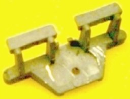
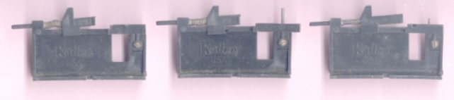
Since many must be assembled in the draft gear box before mounting, holders are useful replacements for a third hand. KaDee offers three jigs for HO. These can be bench mounted or preferably free standing. There is a recess at end to permit the special tweezers to slide in to pickup box. Shown in the locked open position, the spring loaded bars clamp knuckles to hold couplers in place.
Note: Adjust brightness and contrast for optimum viewing.
701 for 4, 5, and 9.___703 for 6, 7 and 8.___702 for 711, 714 and N scale (now Micro-Trains).
The 701 is limited to ear or side screw boxes and by increasing the lateral depth of the ear recesses it can accommodate #4 boxes. The 703 can handle almost any center screw box including 30 series, old MK and the universal adapter plate.
Excellent adjuncts are the 1020 tweezers with offset, parallel, flat tips and notches to clear trip pins. These slide into the jigs to pick up assembled gear and hold it together while mounting. Some repositioning is usually required to clear box lids. With screw(s) lightly tightened to hold assembly, they can easily be slid out.
Often various types of springs must be inserted. KaDee #5 leaf types should be deburred, burnished and checked to assure a flat base. The leaves should be on the outside of the back stop and straight. Since they have a penchant to fly away, coil springs require a spring pick to insert them into shanks or knuckles. Picks have flattened tips with small rounded knobs on either side which are wedged between coils to hold. To allow for some compression toward the opposite end, insert the pick close to one end, by pushing spring against side and bottom of a small box. After working it into a shank, hold it down with a screw driver or knife tip, or finger nail while removing pick. When mounting on knuckle, be sure the coils are hooked over the projections at both ends. Hold spring down when removing pick, just in case. The same technique is used for truck springs. For some other applications hooks can be used to place loops on projections. The one below has a very fine recessing , spring loaded hook which clamps loop against tube end. A fine crocheting needle or hook works well in most cases. To prevent prevent a lengthy search for that precious one of a kind spring; a long, fine sewing thread may be fed through it as a tether.

Note: Adjust brightness and contrast for optimum viewing.
Useful aids for coupler work.
KaDee tweezers.
KaDee spring pick.
Micro-Mark spring pick.
KaDee combination spring pick and talgo adapter installation tool.
Micro-Mark spring hook with fine wire securely clamped.
Jeweler 's (KaDee) concave-convex pliers.
KaDee uncoupler magnet installation jig.
Except for the aggravating hook type couplers, most others can be uncoupled manually, with the big hook, by lifting one knuckle over the other. Several "portable" uncoupling tools have been marketed over the years. Most have been rods with variously shaped tips, which are inserted between knuckles and twisted. If you are lucky, knuckles open and cars can be separated. Although some worked fairly well, eyeballing the insertion point is usually quite difficult. One even had a light. Easier to use, another Y shaped type placed magnets on either side of knuckles, to open them when cars were pushed together. Even if they work, they all have one common fault: they are never around when you need them. No picture, I can't find them.
In spite of any hype, there is no panacea for coupler mounting. A wide selection of couplers and draft gear on hand plus a good sense of reasoning and perspective are required to solve many problems. In some cases, several failures will occur, before a workable solution can be found. By learning from the failures, success rate will improve.
BACK TO COUPLERS
BACK TO METHODS INDEX
BACK TO TEMPLATES, JIGS AND FIXTURES
