Note: Adjust brightness and contrast for optimum viewing.
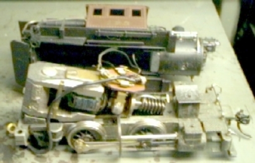
Before, with original PM-1 motor and 26:1 gears.
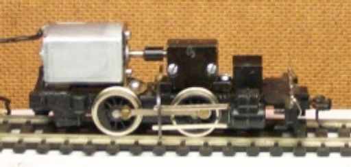
After, with new motor and idler gear box.
Since the Sagami open box motor is no longer offered by NWSL, an alternate method was needed. Fortunately the Jameco 5K RPM @ 12 v, #231731CA , flat can motor fits. When used with a 36:1 gear ratio, this yields about 20.6 SMPH. The motor can not be tilted enough to mesh the worm and wheel. Thus a gear box and universal joint are required. After drawing several impractical methods, a viable solution was found using a modified E-3 Atlantic or Logger, idler gear box. Parts are available from Model Power/Mantua Classics.
First the stripped down frame was prepared for mounting. The two cover plate screw holes were tapped 2-56 clear through and the rear angled motor support was milled down to frame top level, leaving a thin sliver for cab deck plate extension support.
Next the box was prepared for mounting. There are two holes in the frame that are on slightly wider centers than those in the box. The one near the saddle previously tapped through to accommodate the box mounting screw at the top and the loose clearance one that was used to mount the motor. The box mounting holes must be elongated toward the ends to align with the others. A diamond round file was used successfully.
Measuring revealed the worm to wheel axle center was slightly loose for a NWSL 72 DP, 24 tooth wheel; but after trial, it was found to be acceptable, since the loading will be light. The Mantua shafts were measured at about .09 in or likely 2.3 mm. This is slightly small for the NWSL 3/32" or 2.4 mm bored worms, so 3/32" shaft was used. The bushings were mounted in the box to secure them and they were drilled by hand with successively larger bits up to 3/32". This was a snug fit with some drag. The worm was mounted on the shaft, positioned to center with shaft end flush with box end for pressing u-joint cup. The assembly was then clamped in the box with 5 .010" thrust washers to center and reduce play. This was driven dry for several minutes by a rotary tool until free turning was accomplished. The shaft was cut and chamfered to accept the cup with about 1/16 " clearance.
LAYOUT FOR MOTOR MOUNT AND GEAR BOX INSTALLATION.
Vertical line at right is cylinder saddle rear flat.
To permit free turning, the brass, the 24 tooth, 3/32" bore wheel was mounted on the original Mantua shaft with thrust washers to center and reduce side play. This was tested and then after cleaning, lube was applied.
 Caveat: Both drivers must be
requartered to assure they are the same "right angle".
Caveat: Both drivers must be
requartered to assure they are the same "right angle".
Both non-insulated drivers and the old gear were REMOVED from the axles. Then the new gear NWSL 36 tooth, 1/8" bore Delrin reverse worm gear was MOUNTED The driver was not mounted to permit viewing gear mesh during shimming.
It should be noted that the vertical centers of the idler and axle gears are offset slightly. The drawing indicates a shim of about .032". Steel 2-56 machine screw washers are nominally .016", but tolerances are not close. Using two washers at each end mount the box with a screw at the saddle end and a long screw from frame bottom and a nut at the top. Eyeball the mesh. Teeth should not bottom or be close to skipping over one another.
The worm shaft height was measured to determine motor bracket layout. Although it is slightly more difficult to drill holes after bending, quite frequently the bend migrates during the process. A NWSL 2 mm bored horn-ball and a 3/32" cup were used. With straight aligned shafts there is a fairly large longitudinal adjustment limit; but to avoid side pressures on bearings. which may rob power, shaft must be carefully aligned.
A K & S .032 x 1/2" strip was bent into a right angle "L" with the short leg about .230" and the long about .766x" by first cutting a vee groove across it about 1/3 the thickness deep. After this a .090" slot was cut to just less than screw head radius from each end of the short leg, for longitudinal adjustment. The corners were trimmed on a bias to permit access to the crosshead guide hanger, mounting screws. Then a 9/32" hole was drilled at shaft height of .453" to clear bell and two .090" screw clearance holes at 6.2 mm from its center to permit adjustment.
The motor was prepped by cutting its shaft to length from trial fitting and the horn ball mounted at its end. Next by holding in place with the ball in the cup, power was applied to determine terminal polarity. The engine terminal was bent down to contact the can rim and soldered to it. Then the tender lead was soldered to the other.
With the engine terminal at the bottom, the motor was screwed loosely to the bracket and slipped into place with the horn-ball in the cup. The bracket was screwed to the frame with a 2-56 x 3/16" screw, while setting insertion and horizontal alignment. Power was applied and position was adjusted for highest pitch and screwed tight.
Note: The motor requires 2 x .4 mm screws, no longer than 3 mm. Longer ones may damage windings.
The drive wheel was then quartered and mounted on the axle. The other diver was pulled and requartered to assure the same 90 °. Side rods were added and tested.
To clear the gear box a notch must be cut in the bottom of the boiler. The smoke box weight must also be notched to the same size.
Main rods were added and tested and shell mounted. After some running on a roller fixture, track testing completed the project.
This applies to the 0-6-0 Camelbacks also.
BACK TO EXAMPLES
