|
The
adiabatic saturator was designed and constructed at shop 101L of the
mechanical engineering laboratory room of Misamis University, Ozamiz
City from December 2003 to March 2004. The study and evaluation of
the design was carried out after a sequence of groundwork testing.
Most of the materials being used in our design were found in
the shop; like the steel bars, welding machine, drilling machine,
airflow, thermocouple and other materials not available in our shop
such as the water pump, plastic cellophane, and plastic water pipes
were available in the local hardware. The collecting basin was made
up of steel with steel bars on the side and above to hold the water
pipes that sprays the re-circulated water as shown in Figure 1. The
water pump with a 220 watts was placed on the collecting basin and a
plastic water pipes was used to re-circulate the water. Plastic
cellophane was used to cover the collecting basin to the top of the
sprinkler. A duct was connected to the fan/blower that circulates
the cooled/saturated air as shown in Figure 2 & 3.
The adiabatic saturator system pumps water through the
plastic water pipes and are collected by the collecting basin. As
the air passes through the sprinkle of water it undergoes adiabatic
saturation and it is believed that saturated air has a lower
temperature comparing to the unsaturated air. A thermocouple is
placed on the collecting basin to measure temperature referring to
as the wet bulb temperature, one on the exhaust to take the
temperature of the saturated air shown in Figure 4 and another
outside the system to measure the ambient temperature.
4.1
Adiabatic Saturation Process
The following procedure will help to determine and evaluate
adiabatic saturation process:
ž
Taking & recording the ambient temperature (unsaturated
air) every one hour
ž
Taking and recording the water temperature (wet bulb) every
one hour
ž
Taking and recording the exhaust temperature (saturated air)
every one hour
4.1.1
Calculation
Temperature
Drop
=
t1
-
t2
Where:
t1
=
Temperature of entering/unsaturated air (ambient temp.), °C
t2
=
Temperature of air leaving the saturator (exhaust temp.), °C

Figure
1.
A
plastic water pipes above the collecting basin for the re-circulated
water to be sprayed.
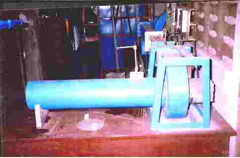
Figure
2. A
duct connected to a blower/fan to collect and distribute the
saturated air.

Figure
3. The
Forward Curved Blade Blower.
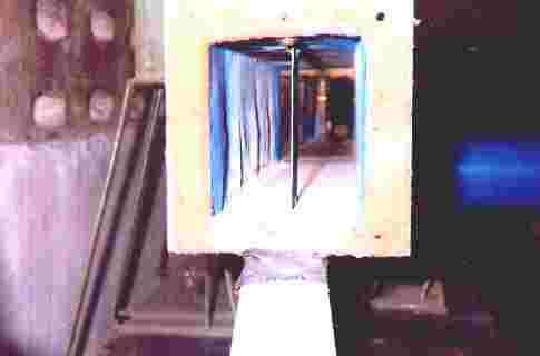
Figure
4. The
exhaust which is connected from the
blower.
This
is where the saturated air exits.
|