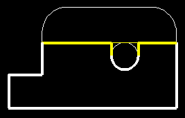
The main problem was to decide how. The MDC pillow block uses a rigid shaft, force fit into one of two holes in the forked end. Both MDC and NWSL replacement step gears are bored to turn freely on the shaft. The two gears making up the new step gear must be fixed to each other by pins, ACC or solder if brass. Alignment and reaming for true turning, would be a very ticklish task, even on a lathe.
Pressing tight fitting gears, with the shaft fed through one fork hole then each gear and finally the second force fit fork hole, can be accomplished very awkwardly. Shim washers should be added during the process.

The third and chosen method was to modify the block by removing the top of the block even with the hole tops and adding retainer straps. (Above yellow line.) Removal was done with a vertical mill, but this also can be done by careful filing after removing the bulk with a rotary burr. Brass straps are cut to fit with screw clearance holes and screwed down into drilled and tapped block holes.
Since the shaft size was 2 mm = .07874 in, a 2 mm drill bit was used to carefully hand ream straight through both holes until the shaft turned freely.
After removing the straps, the bit was used to remove the circular hole tops, (between yellow lines) by pressing upward at a slight angle, to form a "U" slot for shaft entry.
Upon testing with the completed shaft and gear assembly strapped down, some very slight adjustments may necessitate careful touch-up with a fine file. Here the work is far less critical than truing the gears,
Using the fork as a width guide, the frame gear slot is widened by milling or filing. The length is determined by the gears selected. The rounded, milled corners may be filed square for cosmetic effect.
Mounting the block was done by using the original hole with a screw from below, since the flywheel prevented access to a top screw. To help determine distances, mount the geared driver after, installing the new gear. Shorten the length to clear the insulator block, mounted at the frame rear, by about 1/8". Place the assembled mount in the meshed position and use the tapped hole to locate and mark a reference point.
On a scribed frame center line, drill two clearance holes, on either side of the reference point, clear through the frame and mounted cover plate, far enough apart to prevent sidewall break through and bit drift. Using a drill press is best, but careful hand drilling can be done. Then break through the wall between the holes and file to form a slot. This should permit longitudinal adjustment for gear mesh.
With the insulator block still mounted drill a tap hole for a #0 screw, through the block and frame recess, midway between the nut and front edge. Remove the block and re-drill with a clearance bit. The inserted screw will provide a frame ground for motor lead.
While still unmounted solder solid lead wires to the lugs on the motor brush caps, long enough to assure reaching past the frame end when mounted. Motor mounting will depend on motor chosen. This Sagami 10153-9 was shimmed for gear mesh and cemented with ACC. There are no mounting holes and the frame is far too thin to drill without drilling the magnets. They are very hard and may crack. Lube worm and wheel and test worm mesh in both directions at various voltages.
Both insulated drivers and the old gear must be removed from the axles. Then the new gear is mounted and both drivers are quartered and remounted.
 Caveat: Both drivers must be
requartered to assure they are the same "right angle".
Insert both drivers, lubricating the axles, add siderods and track test for free rolling. Then mount block and adjust mesh. Use washer under screw head to reduce possibility of misalignment during final tightening. Test at a low voltage and determine polarity for wires. With the label up the bottom cap should provide forward motion when the frame and drivers are positive. Lubricate the gears and test at a higher voltage. If satisfactory, add side rods and test again.
Bend leads to clear flywheel, shorten and solder to lugs to be placed respectively under nut and screw head.
Add cylinders, boiler and drawbar and test to be certain. Then lacking a Roller Mill, track test with tender on a length of flex track. Add couplers and play with it, switching cars. After some running, measure the speed, which should be about 19 SMPH.
Finish it your way!
For details in making an alternate type PILLOWBLOCK MOUNT.

Note: Adjust brightness and contrast for optimum viewing.

Side views showing motor shims, gear offset and cut down pillowblock.

Top view showing frame gear slot widening and strap.

Top view showing pinion gear which is meshed to driver gear.
Note dirty "worn?" drivers from testing.
BACK TO REPOWER EXAMPLES
