Note: Adjust brightness and contrast for optimum viewing.
Before with original PM-1 motor and 26:1 gears.

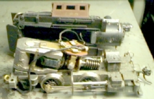
First attempt at this method on switcher, showing some lack of forethought in haste.
Note normal offset from vertical in gears to permit mesh adjustment.
Although the finished product performed very well, better planning was definitely indicated. The pillow block and motor mount were two separate pieces. A short fork with soldered bearings was screwed down at the front, while the motor was shimmed and glued to a sheet of Plaststruct and screwed at the rear. This does dampen motor noise to some extent. Since flywheels were not purchased yet, none was added.
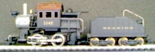
Original showing PM-1 motor bearing above right first driver.
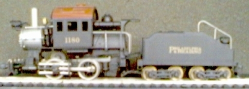
First try regeared showing reduction gear and bearing above first driver.
Plastruct motor shim visible under cab and firebox.
After enjoying the fruits of my labor, afterthought suggested several improvements. Drawings were drafted on X-CAD with many alterations. Correcting mistakes is much easier on my AMIGA. The motor could be moved forward and the PM-1 motor mount could be milled off at the rear, permitting clearance for a flywheel. The final drawing follows:

Complete layout for repowering which drops speed from 104 to 19 SMPH @ 12 V.
Vertical dimensions at line levels are referenced to axle center.
This applies to the 0-6-0 Camelbacks also.
For details in making PILLOWBLOCK MOUNT.
Both non-insulated drivers and the old gear must be REMOVED from the axles. Then the new gear is MOUNTED and both drivers are QUARTERED AND REMOUNTED.
 Caveat: Both drivers must be
requartered to assure they are the same "right angle".
Caveat: Both drivers must be
requartered to assure they are the same "right angle".
Next drivers are mounted in frame and axles lubed with only siderods added. Then the assembly is checked for bind by rolling on a length of track.
Next the siderods are removed and the completed pillowblock is aligned and mounted. The mesh and alignment are checked in both directions by applying a low voltage with test lead. Correct if necessary. Voltage is increased to about 12 V to test again. Remount other driver and siderods and test.
Assemble including boiler with weight and connect to tender for track test. If all goes well, its ready for playing and finishing.
BACK TO EXAMPLES
