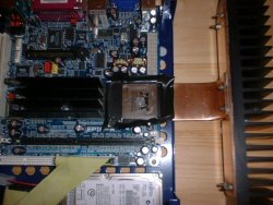
Masking the CPU and adding the goop |
Firstly the old factory heat sink was removed, cleaned thoroughly
with a citrus based solvent and a blob of Arctic Silver
applied. I then masked the edges of the CPU with insulation tape to
stop any spillage off the edges coming in contact with the motherboard.
As you can see the main heat sink has a length of copper
bolted to the edge with another piece of L shaped copper bolted through
the heat sink and the copper base. This is to aid heat distribution
through the length of the heat sink. Yes, there is a
thermal compound between the copper and the sink! The thermal
resistances gained through adding further interface materials only
gives a 1/r addition. (so it's well worth it). You can see in this
picture that the holes drilled in the base are aligned around the
motherboard to encourage the air to be drawn through the case.
|
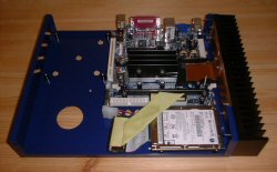
Align
The Copper Spreader |
The new sink is moved into position and
bolted to the edge of the case via 4 M3 bolts. All the copper
surfaces have been lapped with differing grit pieces of wet and dry
(upto 1500) which helps reduce resistances. (and makes it look nice
and shiney!) |

Another View
|
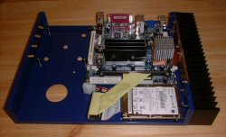
Add
The
Second Heat Sink |
A second heat sink was then added, it's not actually
needed as the main heat sink can easily dissipate the heat
required, but i liked the look of it and just-in-case the ambient
temp in the room (not the case) ever went over 35 degrees C,
this would stop the unit overheating by adding some more capacity.
The mountings supplied were 'modified' with a drill to fit the cpu!
The screws where then tightened to squeeze everything together.
|

Close
Up Shot! |
This is a close up showing the final heat sink
assembly. Once it had all been tightened down, I carefully
removed the masking insulation tape from around the heat
sink, none had escaped! | |


 CPU Heat Sink
Installation
CPU Heat Sink
Installation
 Previous Stage
 mr_pdt@yahoo.co.uk