Secondary Componets Installation

FT Transmitter and Theater 550 Pro Card Fitted!

The FM Transmitter board is bolted into the four mounting feet while the TV card is mounted on two 20mm spacers. (back plate removed from the card and the 3m holes reused). A further spacer foot is added towards the back of the card to reduce the stress on the front two mounts. A flexible PCI riser is used to connect to the motherboard. 

There is approx a 4mm gap between the TV card and one of the FM Transmitters capacitors! The vents on the side of the case allow the Theater 550 to remove some of its heat (it does get quite hot!).


Optical Drive & Power Supply Fitted!

The CD is held in via two screws on the left hand edge and two  'modified' curtain rail brackets. These L shape pieces of steel had one part shortended and an M3 hole drilled. A 20mm spacer was attatched as the foot. (See rubbish diagram!)  Another similar assembly supports the rear of the drive. The CD facia bezel is refitted. (not shown)

The power snap in is added and power cables routed as required. As you can see from this picture the wires connecting the button and leds on the case have been connected also.


Rubbish Diagram of mounting foot assembly

Overhead View

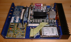
I added a piece of thin padding under the IDE cable going to the CD/DVD to stop any rattling and also taped a small piece of copper ontop of the HardDisk as the spinning motor was causing a resonanse frequency with it's own case. (very high, not noticable above 4 inches away). A small weight ontop stops this nicely tho.

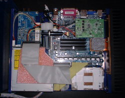
Sorry for the change in surface for these last two pictures. I know the black doesn't really work as a background, but it's the only surface (I had clear) that I could use.


Previous Stage Next Stage

mr_pdt@yahoo.co.uk © Paul T 2004 : Not to be reproduced without permission.