| |
|
|
|
 Home
Track
Building
Routing
1
Home
Track
Building
Routing
1 |
| |
| Constructing the Track
- Routing, part 1 |
With the plan and the jigs completed,
it was time to get started.
The track surface was 1/2" MDF,
available from the local lumber yard
for about $20 a sheet.The triangular
legs and the cross members were made
from 3/4" A/B plywood.
The MDF was soft; therefore cut easily.
When routing the MDF, a lot of dust
is generated - I ended up buying a shop-vac
and a dust mask.
|
| Routing the curves |
All the curves were routed using
the two "curve jigs"
described earlier.
|

Cutting the inside of a curve
blank.
|
- Mark the center of the curve.
- Using a protractor, draw
lines extending from the center
of the curve to the edges
of the curve.
- Drill a pivot hole in the
MDF at the center of the curve.
- The jig is placed in a pivot
hole in the MDF.
- Route the outer edge first,
then the inner edge.
- A clamp holds the pieces
together to make cutting the
last few inches easier.
|
|
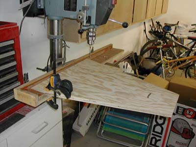
| Routing the edges |
Without a circular saw, a straight
edge and router may be used to
cut the edges.
|

With the straight edge still in
place, the completed curve blank.
|
- The straight edge is clamped
to the curve, parallel to
the line previously drawn
for the edge, allowing for
the offset required by the
router base.
- The straight edge was always
placed on the "track
surface" side of the
edge line.
- The router was run along
the straight edge (already
complete in the photo)..
|
|
| Straights |
All the straights were cut on a table
saw. The MDF sheets were 49" wide,
since the track sections were 23 1/2"
wide, the panel was first ripped at
24 1/2". With a more managable
piece, a second pass was made on the
table saw, trimming the straights to
the exact width..
The edges of the straights were cut
with a straight edge and router, using
the same principles as cutting the edges
of the curves. |
| |
| Cross members
|
The cross members were cut from
3/4 plywood. They were 3 1/2"
tall and the same width as the
track surface.
|
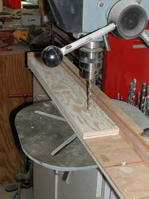
Drilling the first hole.
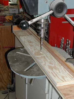
Drilling the second hole.
|
- The cross member is placed
against the left edge of the
jig, the first hole is drilled.
- The cross member is moved
to the right in the jig, placing
the first hole on the dowel.
The second hole (middle of
cross member) is drilled.
- The cross member is moved
to the right in the jig, placing
the second hole on the dowel.
The third hole is drilled.
- Before removing from the
jig, draw an "X"
in the upper right corner
of the cross members. When
the cross members were attached
to the MDF sections, the cross
members were oriented so all
the Xs were on the same side,
providing for accurate alignment.
- The holes were 1/32"
larger than the bolts used.
This allowed the adjacent
sections to be adjusted so
the surfaces were even.
|
|
| Attaching the
cross members |
The sections are joined by bolting
the cross-members from the adjacent
sections together with 3 bolts.
The cross members also anchor
the side boards.
|

The "lead on" with the
third cross member clamped and
glued prior to drilling the pilot
holes.
|
- Place wood glue on the edge
of the cross member and the
bottom of the track surface.
- The face of the cross member
must be flush with the edge
of the track surface.
- Clamp the cross member in
place.
- Drill the the pilot holes.
- Secure the cross member
with drywall screws.
- Be sure the spacing for
the screws will not interfere
with the slots or braid..
|
|
| Legs |
The legs were made of 2 triangular
pieces, joined by 2 bolts. One
triangle had a long, vertical
slot; the other had a pivot hole
and a curved slot. When joined,
the leg was adjustable both vertically
and angled. With so many pieces,
this was a time consuming step.
Since the track had elevation
changes, the legs were divided
in to 3 categories - low, medium,
and high. The same principles
were used on all the legs, the
length of the pieces varied among
the 3 types - all the legs had
about 6" of vertical adjustment
and 15 degrees of tilting adjustment.
|

Routing the curved slot in the
leg which controls the tilting.
For the upper triangle, holes
were drilled for attaching to
the cross member using the same
jig. Since the legs were 3"
narrower than the cross members,
a 1 1/2" block was placed
in the left corner of the jig.

A completed leg attached to the
cross members. The curved slot
in the upper triangle controls
the tilting, the vertical slot
in the lower triangle controls
the height adjustment.
|
- A grid of the trianglular
pieces was drawn on a 4 x
8 sheet of plywood, alternating
the orientation to minimize
waste.
- For the upper triangle,
the piviot hole was drilled
first, the tilting hole was
drilled second, the small
curve routing jig was used
to cut the tilting slot. The
3 holes for attaching to the
cross member were then drilled.
- For the lower triangle,
one hole was drilled, a straight
edge and router were used
to cut the vertical slot
- The edges of the legs were
smoothed using a 1/4"
round-over router bit..
- For more support, "fender
washers" were used for
the 2 bolts holding the triangles
together.
|
|
|
| |
| |
|
|