
SOURCES
OF MATERIALS & PROCESSING TECHNIQUES
3.1 SOURCE OF MATERIALS:
Crude oil is the basic source of aviation fuels. Both aviation
gasoline and jet fuels are obtained from the fractionation of crude oil.
Crude oil normally contain 10% W kerosene (JP-1) and about 45.5%
only about 0.2% finished aviation gasoline.
The components are different in different types of crudes and from
place to place.
The different types of crude oil are as follow.
Aeromatic having general formal C6H2n-6. where n is greater than
or equal to 6 ( n ³ 6 ) contain six carbon
atoms in the form of hexagon shaped ring & are un-saturated ring compounds.
e.g. C6H6 (Benzene), Toluene (C6H5CH3) etc.
3.2 CRUDE OIL YIELD:
A barrel of crude oil (42 us Gallons) will yield slightly more
than 44 gallons of finished refinery products. This is due to the reduction
in density of many crude components during processing. Here is the break
down from a "typical barrel of oil".
3.3.1 DISTILLATION:
The separation of mixtures of liquids into their component parts is one of the major processes of the chemical and petroleum industries, and distillation is the most widely used method of achieving this end.
Distillation is basically a separation process in which a liquid mixture is separated into their components on the basis of their boiling point or relative volatility.
In practice, distillation may be carried out by either of two principle methods. The first method is based on the production of a vapour by boiling the liquid to be separated and condensing the vapours without allowing any liquid to return to the still, there is then no reflux. This type of distillation is called the flash distillation.
The second method is based on the returning of part of the condensate to the still under such conditions that this returning is brought into intimate contact with the vapours on their way to the condenser. This special method of distillation is called rectification. Rectification is the enrichment of the vapour stream as it passes through the column in contact with reflux. The usual source of reflux is the condensate leaving the condenser. Reflux is some times provided by partial condensation of the over head vapour the reflux then differs in composition from the vapour leaving as overhead product.
Rectification is achieved by an arrangement known as a fractionating column which enables successive vaporization and condensation to be accomplished.
FRACTIONATING COLUMN:
The fractionating column is a typical distillation equipment consists of cylindrical structure divided into sections by a series of perforated trays, which permit the upward flow of vapour. Liquid on each plate can run through a weir and down comer to the plate below.
The top edge of the pipe (down comers) forms a weir. The height of the weir pretty well fixes the height of the liquid on the tray or the weir maintains a minimum depth of liquid on the tray, nearly independent of the rate of flow of liquid. Vapour flows upward from tray to tray through perforations. The over head vapour is passed to a condenser and the resultant condensate split by the reflux divider some being with drawn as a product and some being returned to the column as reflux.
The use of reflux increases the purity of the overhead product. The reflux entering the top of the column is often at the boiling point.
The lower boiling components are drawn from the
top of the column as over head product and the higher boiling components
are recover from the bottom as bottom product end residue.
MODERN CRUDE OIL DISTILLING UNITS:
The products separated in the crude oil distilling unit of a modern refinery may be broadly classified in order of decreasing volatility into gases light distillates middle distillates and residue.
THE GASES:
The gases consists chiefly of methane, ethane, propane and butane. The first two are used as refinery fuel or may be supplied together with other refinery gases for making town gas. Propane and butane may be liquefied by compression and marketed as liquefied petroleum gas (LPG). Butane may to some extent be added to gasoline.
LIGHT DISTILLATES:
The light distillates comprise fractions which
may be used directly in the production of motor and aviation gasolines.
The heavier higher boiling point fractions in this range are the lighting
heating and Jet engine kerosenes and the feed stocks for reforming process.
The special boiling spirits and wide spirits are obtained by further distillation
of an appropriate gasoline fraction in a special plant designated to give
a high degree of fractionation, so as to produce the narrow boiling ranges
required. The heavier fractions falling with in the gasoline range are
sometimes referred to as naphthas.
MIDDLE DISTILLATES:
The middle distillates are use as gas oil and diesel fuel and also for blending with residual product in the preparation of furnace fuels. The distillates used as feed stock for cracking purposes may be obtained from middle distillate range.
RESIDUE:
The residue consisting of the components that are not removed as distillates, is used as fuel oil or for the manufacture of lubricating oils and bitumen.
The general scheme of crude oil
distillation and a crude oil distilling unit is shown in the figure. 3.1
The crude oil passes through heat exchangers to the furnace, where it is raised to the distillation temperature, approximately 300 to 350oC (570 660oF), depending upon the feed stock and the products to made. The hot oil and vapours then enter the first fractionating column.
Part of the top products from the column after condensation is used as reflux the remainder is transferred to the second or light distillate column. Heat is supplied to this column by a reboiler. The top fraction comprise gasoline and lighter products and the bottom product is kerosene.
Butane, propane and lighter products are separated under pressure in the debutanizer and de propanizer, heat again being supplied by reboilers. The removed of the very volatile products from gasoline fractions in this manner referred to as stabilization and the process is used not only in crude oil distillation but also in the recovery of liquid products from natural gas and in the fractionation of the gases and volatile liquids from cracking units.
The gasoline from the bottom of the debutanizer is further fractionated into light and heavy gasoline; the later being used if necessary for the manufacture of while spirit or special boiling point spirits are subjected to thermal or catalytic reforming.
Side streams are taken from intermediate points in the first column and stripped in small stripping column to produce light and heavy gas oil. The residue from the bottom of the crude oil column may be used as fuel oil or it may be redistill in a vacuum unit to produce as distillates ( gasoline, kerosene), gas oil lubricating or catalytic cracking feed stock.
The fractions or side streams must meet specification that are imposed by further process or by buyers. The boiling ranges and cut points as shown in the table 3.1 are one of the more basic specifications. The degree of separation in a fractionator is indicated by the "cut point" or intersection of the adjacent true boiling point or TBP-curves, shown in the figure 3.2.
TABLE: 3.1
REFINERY NOMENCLATURE OF DISTILLER FRACTIONS.
|
|
Range |
Range |
IBP EP |
|
|
|
|
|
|
|
|
|
|
|
|
|
|
|
|
|
|
|
|
32 27 |
88 104 |
normal LSR max LSR |
|
|
|
|
32 27 |
88 104 |
max jet fuel min reformer |
|
|
|
|
166 193 |
249 271 |
maxjet 50 max gasoline |
|
|
|
|
249-271 |
321 321 |
max jet max kero |
|
|
|
|
|
|
|

The general sketch of petroleum distillation products and there boiling ranges shown below.


The aviation fuels (aviation gasoline and Jet
fuels) obtained from crude oil distillation are not the finished product
for marketing but require some further processing such as dehydrosulphurization
desalting and blending etc to improve the performance and quality. Beside
these for aviation gasoline isomerization cyclization and aromization is
required to increase the octane rating.
(a) SWEETENING PROCESSES:
All petroleum products contain sulphur compounds in term of various types of mercaptane. These mercaptance are harmful for the combustion engines and other systems. So it is essential to remove these undesirable sulphur compounds into some acceptable limits as per API limits. Sweetening process may be define as the removal of sulphur and its compounds such as hydrogen sulphide, mercaptances etc from the petroleum products.
There are various processes for the removal of these mercaptances. However the important and world widely used of these methods are.
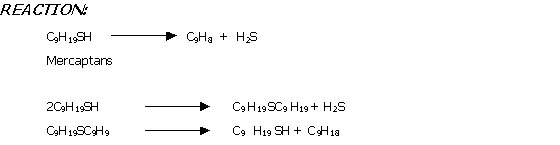
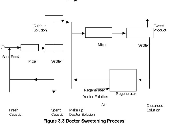
In this process mercaptanes present in the petroleum
products are converted in to disulphide by treatment with doctors solution
(Sodium plumbite solution) and sulphure. Lead sulphide is regenerated to
sodium plumbite by air blowing the solution.

Doctor sweetening process is carried out at 65oC "20 parts of Doctors solution are circulated per 100 parts of lead. Feed and doctor solution are contacted for 30 sec before sulphur solution is added and the total mixture is then stirred for 5 15 minutes. Sulphur addition should be controlled as excess sulphur produces polysulphides [ Pb (RS)2 + 2S PbS + RSSR ] which reduces octane rating of gasoline and lower the burning quality of distillate fuels. Regeneration of Doctors solution is carried out at 80 110oC and 1 7 atmospheric pressure.
Merox sweetening is a chemical process by which
mercaptans Naphtha and kerosene (JP -1, JP 4)are extracted from them
by contact these products with caustic solution which contains merox reagent
no. 2 and 1 catalyst respectively in it.
Caustic washing is the first step in sweetening
process which is carried out in a vessel containing 10oBe caustic
solution. It is operated half full with a caustic solutions under controlled
temperature and pressure during which the following reaction takes place.

The non corrosive Naphtha from the top of pre washer enters a
horizontal vessel called the settler, where the entrained caustic or sodium
sulphide are knocked out from naphtha.
The non corrosive naphtha which is also free
of caustic and sodium sulphide come out from the settler and enters an
extractor tower containing 20o Be caustic solution, containing
150 250 ppm of merox reagent no 2 catalyst in it. The low molecular
weight mercaptan extraction takes place in the extractor and sodium merecaptides
are formed as per following chemical reaction.

The naphtha from the top of the extractor
enters a 20 ft x 5ft reactor from the top 17 ft height of this reactor
is loaded with a catalyst which is activated charcoal impregnated with
merox reagent
no. 1 catalyst. Control quantity
of air is injected to the reactor feed to supply
oxygen needed for oxidation of mercaptans to disulphides according to the
following reaction.

Sweet naphtha comes out from the bottom of the
reactor and enters a horizontal vessel called the settler to minimize the
chances of entertainment of caustic with a naphtha product.
Before sending sweet Naphtha to storage it is
passed through a sand filter to be absolutely sure that no caustic remains
in the product as this naphtha is use for JP 4 and gasoline blending
.
The disulphide is separated in the disulphide separator and the morx reagent no. 2 catalyst separated is pumped from the bottom of the separator to the extractor again.
(b) KEROSENE MEROX UNIT:
The kerosene contains H2S and high molecular
weight mercaptans only. Therefore, after giving it a caustic prewash for
neuhallizing the H2S, the kerosene is feed to a sand filter
to remove entrain caustic.
The Kerosene from the sand filter enters two
parallel reactors from the top. Control quantity of air is injected at
the inlet of the reactors. Special arrangement has been made to ensure
complete mixing of air with the feed. The catalyst of the reactors and
the chemical reactions have already been discussed under naphtha merox
unit.
Sweet kerosene comes out from the bottom of
the reactors and enters a settler from the top to remove entrained caustic
from the product.
Kerosene comes out from the top of the settler
and enters a water wash vessel which is operated 50% full of water to absorb
any impurities and merox caustic entrained with the kerosene.
Sweet kerosene from the top of the water wash vessel is although
free of caustic but it now contains traces of water which is undesirable
as this kerosene is also used for JP 4 blending. Therefore it is passed
through a salt filter. The salt absorbs the water moisture from kerosene.
After the salt filter the product still may
contain small amount of gum forming compounds which are objectionable in
JP 4 blending. These impurities are removed by passing the kerosene through
a clay filter which absorb the impurities. Therefore, kerosene coming out
from the salt filter enters a 33ft high clay filter from the top. The filter
is filled with a 30 ft high layer of 30 -60 mesh fullers earth type clay.
Now the kerosene product is sent to storage for selling as illuminating
kerosene or for JP 4 blending.
It is often necessary to remove suspended or
dissolve water. Cooling can assist in decreasing the amount of dissolve
water and the suspended water is removed by settling and coalescing. Dissolve
water can be reduced by passing the hydrocarbon stream through a suitable
hygroscope absorbent, which can be regenerated; either a solid absorbent
such as activated alumna or a liquid absorbent such as diethylene glycol
may be used. In the later case a "water dew point" is replaced by " glycol
dew point".
The cheapest way is to pas the products through a bed of calcium chloride or a similar drying agent which is replaced when no more water can be absorbed. The dew point reduction attainable with calcium chloride is rather small.

3.3.3 STEP III BLENDING:
Blending is a physical process in which accurately measured or weighted quantities of two or more compounds are mixed together to form a homogeneous blend. The components may be all petroleum fractions or may include other materials e.g. fatty oils, dyes functional additives referred to collectively as "additives" in proportions from a few parts per million to ten (10) or 20% w. the blends will be formulated to have the required properties for particular applications and will usually be required to meet appropriate marketing specifications.
Blending is required for all oil products of all kinds. In case of aviation fuel for gasoline as marketed is usually a blend of several refinery grades generally contains lead antiknock compounds and many other additives.
Jet fuels of various grades are obtained from blending
of various refinery products, e.g. kerosene and full range naphtha and
some other additives to enhance the quality and performance. The various
additives are corrosion inhibitor anti-icing inhibitors and static dissipaters
etc.
×
Ø
|Chemical|
Faisalmurad|Guest book|
Comments|WEBMASTER|D.C.E.T|N.E.D uet|Title|
Certificates|MAIL Us|