Beginning of MDT
"When Version 1 of Autodesk's Mechanical Desktop was introduced back in March of 1996, it was criticized as being a combination of AutoSurf and AutoCAD Designer with a few extra features tossed in. Many felt it was just an effort to distract users from the recently released SolidWorks and Solid Edge. However, with every upgrade since then, the program has been steadily improved. This trend continues with Version 4, released in September of 1999." (Quote from an article by Joe Greko Nov 1999).
MDT began for me with MDT4 which was a milestone in terms of core capabilities (think A2000 vs R14) while MDT5 and MDT6 had features and improvements which were not hugely signifigant to me (think A2000i and A2002). Bending is all I'd like from MDT6 (ribs and embossed text I can do in MDT4 and I can transfer parts between assemblies and subassemblies in the browser with a bit of judicious writing out and copying back in). To me MDT is AutoCad on steroids and I'm happy leveraging my AutoCad knowledge. Remember you get given AutoCad (vanilla) AutoCad Mechanical and, these days, even Inventor is included so all bases are covered.
Case For MDT
I use AutoCad and MDT. I have recently used Rhino3D and Intellicad. That's it. I don't do 5000 part assemblies and I need to be able to do some surfacing. No one was as able to give me a case for abandoning Autocad/MDT for Inventor when you had to buy them separately so I don't see that AutoDesk giving away Inventor free or for chump change alters the position in broad terms. Further, I suspect Inventor is not as intuitive to learn as AutoDesk marketeers claim and issuing a *new* Inventor release every six months (seven in three years!) raises more concerns. Update: Inventor 6 has extensive surfacing and the functionality in general is said to be finally comparable with MDT (from an MDT users perspective).
Below are some articles on MDT by respected practitioners as well as journalists. The emphasis is on why MDT is still a force while achnowledging the standing of Inventor (they do not have enough details to provide tutorial value):-
www.cadenceweb.com/../ An MDT Users Look At Inventor5.3. John Wilson Aug 2001.
www.cadenceweb.com/../ Nov 2001 Cadence article on MDT6 by John Wilson. Rationale for choosing MDT as opposed to Inventor.
www.cadserver.co.uk/../ Oct 2001 Cadserver (UK) article on (AutoCad Mechanical and) MDT6 features by Al Dean. Note in the last para the expressed hope that some of the MDT6 functionality discussed could be bought into Inventor(5 assumed).
www.cadonline.com/../ Oct 2001 Cadalyst MDT6 review by Bill Fane (British Columbia Institute of Technology). Theme is powerful mature product still introducing improvements. Has references to the Powerer Pack (ie standard parts such as springs for example).
www.caduser.com/../ A Nov 2001 Caduser (UK) article on the introduction of MDT5. Mentions Ribs from single line sketches, text on surfaces and bending whichs helps me understand what came in MDT5 (I have only used MDT4 and MDT6). Refers to surfacing analysis tools. Quotes AutoDeskers at a show saying they hoped to have equivalent funtionality to MDT in Inventor6. Comments about number of Inventor releases.
cgw.pennwellnet.com/../ Dec 2000 Computer Graphics World MDT5 review by John Wilson. References to surfacing and surfacing vs solidmodelling. Refers to 'lines and arcs' as basis for single line sketchs for thin extrusions (eg ribs). Refers to a Pattern (as opposed to arrays) and being able to form a spiral-like pattern around an axis.
www.cadenceweb.com/2001/0401/thirddimension0401.html Apr 2001. MDT5 Surfacing role. Surfaces used to shape a solid to achieve a solid that could not be created with solids tools. Says surfacing tool improvements were introduced in MDT5 after a *number of releases* which did not add to surfacing capability. Lists the pre-MDT5 surfacing tools and lists separately those introduced in MDT5.
Some tutorial worth but kept here in the Case For MDT because if discusses surfacing, which was a capability (at least prior to IV6 with the introduction of Shape Manager) distinctly lacking in Inventor.
www.cadsystems.com/../ ** Has not come up from 13April03 to 15July03. See Google cache local file.**
MDT4 article by David Byrnes. Discusses the historical origins of MDT.
(was based in Bowen Island, BC in 1997. Was dbyrnes@cadsystems.com in June 2000.)
acadmdt/davidburns/davidburnsmdt4.html The Google cache of the CAD Systems Jan 2000 article on MDT4 now held in a local file.
www.cadchat.com A Forum. Go to MDT section and see the discussion on use of MDT in 2D role doing fixtures in conjunction with Rhino3D Ver2. Anticipated 2Dlayout improvements in Rhino3D Ver3.
Link to Posting
**Requires printing out and a local summary made. No good as is and the posting could be removed.**
## 400 Not Found 5June03 to 15July03 ## And I do have the hard copy if I sought through all the odd printouts.
MDT Links
![]()
www.mymcad.com aka Mad Drew's MCAD Connection.
Click on MDT up in top navbar. See MDT Tips and Tricks, FAQ's and Resources (also has Inventor section). Good Canadian site.
acadmdt/drew/embossedtext/embossedtext A local file of a tip on how to produce embossed text in MDT4 (and presumably A2000 through to A2004). Embossed text is avaliable in MDT5,6,2004.
acadmdt/drew/linefacesplits/linefacesplits.html A local file of a tip on how to use the Line Splits and Face Split commands.
acadmdt/drew/index.html A local file of some better of his tips and Pico site search.
www.cadforum.cz/cadforum_en/default.asp Heaps of Autocad/MDT tips **duplicated in MDT My Tips and Memory Joggers and AutoCad (Some Other Interesting Links).
support.drury.edu/docs/autodesk/Mechanical%204%20Getting%20Started.pdf
Complete official AutoDesk Getting Started In MDT4 manual.
support.drury.edu/docs/autodesk
To refer to or print out all the Autodesk pdf product manuals that are on-line at drury.edu. None are zipped for downloading. Lots of stuff but of particular interest to me is to refer to is:-
AutoCad 2002 Customisation Guide (198 pages). Good -well worth printing out.
AutoCad 2002 Command Reference (604 pages). Good -just refer to or print out odd pages of interest.
** Link duplicated on my AutoCad page -Acad2002 section.
ftp://adeskftp.autodesk.com/WebPub/education/manuals To download Autodesk manuals from Autodesk. Includes the MDT4 Tutorial Manual you get in the box and a 406 page MDT4 Command Reference you dont get in the box. There is other stuff.
mdt4commref.zip 3.03 Mb Command Reference. (406 pages). Invaluable. Does not come in the Box. Needs printing out. Held by me for back up in c:\ student/adesk_downloads.
mdt4gsg.zip 1.95 Mb Getting Started -Good (same as drury.edu but zipped hence downloadable). Included in MDT4 box.
mdt4ig.zip 1.75 Mb ? Installation Guide -Bit useless unless you need it for some reason. Included in MDT4 box.
mdt4tut.zip 0.851 Mb I downloaded this once to confirm it was the tutorial manual that came in the MDT4 box. When I downloaded a second time in the lab, Acrobat would not open it. If you have MDT installed the .dwg files for these tutorials are in the support folder (same same MDT5,6).
** Link duplicated on AutoCad page.
www.autodeskpress.com/../ Thompson Learning. Leads to MDT4 and MDT5 sample chapters (and Autocad).
www.autodesk.com/us/eol_home.htm ## Note: Site had no content for Mechanical Desktop on 25 Apr 2003.
The AutoDesk Point A has merged with their main website. From this page you can access their Support (not much), Articles, Tips and Object Enablers (ie tutorials) for their products.
MDT Articles
Below are some articles on MDT by respected practitioners. Considerable portions are detailed enough to be useful as tutorial material (Index of acadmdt folder):-
www.cadenceweb.com/2000/0800/thirddimension0800.html Aug 2000 Cadence article on MDT features created from profiles by John Wilson. Extruding, revolving, sweeping and lofting. Excellent informative article/tutorial on termination options particularly (for me) the little used sweep along a 2DPATH or 3DPATH. Suit MDT4,5,6 (probably MDT2004 too).acadmdt/mdt_tuts/sweepterminations/face_terminations.html Local version
www.cadenceweb.com/../ Feb 2001 Cadence article on MDT5 by John Wilson. Open profile extrusions, ribs and bending. From MDT5 a profile can be a single line or arc (Open Profile). Demonstates use the three commands-AMEXTRUDE, AMRIB and AMBEND -allowed with open profiles. Good. For MDT5,6 (and presumably 2004).
www.cadenceweb.com/2001/0601/thirddimension0601.html Making use of the 3DOrbit command including making models semi-transparent when shaded to aid visualisation and selection at the same time. Also section on rendering and materials. Very good. (John Wison Jun 2001). MDT5,6 (probably MDT2004 too).
acadmdt/mdt_tuts/render/render.html My local copy of this excellent article/tutorial on visualising and rendering in MDT.
www.cadenceweb.com/magazine/thirddimension Other CadenceWeb ThirdDimension articles by John Wilson. **Includes MDT stuff I'm sure I have not looked at and Rhino3D which is my surfacing and file conversion tool of choice.
www.cadenceweb.com/2000/1000/thirddimension1000.html John Wilsons October 2000 Cadence concise article on Scene mode.
www.cadenceweb.com/../ Review of MDT4 (applies to MDT4,5,6) by Joe Greco. Includes describing the use of:-
*RClick during drawing with polylines (pline or pl) to avoid pecking at the keyboard to nominate arc etc.
*Length of blue extrusion direction arrow is the value entered in the extrusion input box. Visual design aid.
*Grip editing a profiled sketch to make gross changes without trying to drive it there with dimensions.
*Use of AmPowerDim and AmPowerEdit to pickup existing dimensions. I note that editing (modifying) a dimension equation using AmModDim requires rewriting the entire equation at the command line while with power editing you can make only the necessary changes in a dialog box. Similarly with new dimensions using AmParDim you have to write out a whole new equation while with power dimension you nominate an existing dimension equation and edit it only as necessary (AmDimDsp for display as equations and, if you want, AmVars to set names for variables ie Width instead of d2 for example. See the 'P=' flyout button on the 2D Constraints toolbar).
www.cadonline.com/../ Cadalyst article on the improvements to MDT5 over MDT4. By Bill Fane, a CADALYST contributing editor who teaches at the British Columbia Institute of Technology. Article originally appeared in the March 2001 CADALYST Magazine.
acadmdt/bfane/mdt5improve/mdt5improve.html Local backup of article. Guidance is valid for MDT 5,6 and probably 7. Main points addressed are transparent 3DORBIT command (returns you to the middle of whatever command you were in when you decided to orbit the model). Ajusting lighting ambience and direction to improve viewing during orbiting. Making the browser go up and down like a blind from a top toolbar like position. Coloring features like holes for example differently to the main part colour. Open profiling for thin extrusions, folding, embodssing and more.
www.cadonline.com/../ Cadalyst solutions article (a tutorial) on how to produce 3D raised (or embossed) text in AutoCad generally and MDT prior to MDT5 when the facility was provided. By Bill Fane, a CADALYST contributing editor who teaches at the British Columbia Institute of Technology. Article originally appeared in the May 2000 CADALYST Magazine.
acadmdt/bfane/3dtextobjects/3dtextobjects.html Local backup of 3D Text tutorial. Guidance is valid for AutoCad 13,14, 2000, 2000i, 2002, 2004 and MDT1,2,3,4 based as appropriate on exploding text using Bonus Tools or Express Tools or a WMFIN, WMFOUT workaround. Note MDT5,6 and 7 has the facility to produce the solid text and AutoCad 2004 provides the A2000 Express Tools that were removed in 2000i and 2002 so A2004 users should follow the A2000 guidance. Also note there is another tut on this page which refers to using Word 97/2000 to provide more options particularly with the availability of text which is "hollow" (some of the SWIS ones) and the Word Art facility (if you are so inclined).
acadmdt/bfane/3dtextobjects/bonus_express_tools.html Some notes on how to migrate R14 Bonus Tools and A2000 Express Tools to A2000i or A2002 -aj.
See also similar acadbonusexpress/migrate_express_tools.html Migrate Express Tools
See my acadbonusexpress/index.html Index of AcadBonusExpress Folder And Related From Elsewhere where I gather together everything I can on Bonus and Express tools including a link to download the A2000(MDT4) Express tools for use in A2002(MDT6). And eventually info about the Express tools that have reappeared in A2004 although some have been incorporated into the main package I understand.
Note: There is some duplication of these links in the A2002 section of the AutoCad page.
MDT Tutorials
The following have definite tutorial value (Index of acadmdt folder):-
sgilogo/index.html Index Of SGI Logo Folder. Awaiting a home after evaluation. At present this call is in Autocad, Customizing (script), MDT and Rhino (where it all started because a tut link went dead.
acadmdt/mdt_tuts/constraintoboltcenter/constraintoboltcenter.txt Postings detailing a solution to constraining a (separate) threaded hole to a bolt circle. Includes a reference to MyCad ie sgilogo/index.html
pointa.autodesk.com/../ Bill Fane's build a frame Power Pack tutorial. Uses steel sections to make a frame and constrains it so the frame can be resized. ## Does not come up anymore. ##
acadmdt/mdt_tuts/powerpack/powerpack.html Local file. Good tutorial. Fortunate that I saved it. For MDT4,5,6 and presumably 2004. This version is original for ANSI users (ie United States and Burma).
acadmdt/mdt_tuts/powerpack/powerpack_iso.html Local file. Good tutorial. Fortunate that I saved it. For MDT4,5,6 and presumably 2004. This version is mildly modified and is intended for those who work to Isometric (the world less the United States and Burma).
usa.autodesk.com/../ A Bill Fane Autodesk website tutorial on FEA in MDT.
acadmdt/fea/fea.html Local version.
hera.eeginc.com/autodesk/au/session_list.cfm Dec 2002 Autodesk University Handouts (also on Inventor page).
View any session handout (pdf) or download all the handouts in your area of interest, such as
Manufacturing (22.1Mb zipped!) or
Education for example, in one zip file.
There is so much that would interest any Autocad user like Undocumented or Tips and Tricks but here are the direct links to the six MDT6 presentations (and some more I could not resist):
hera.eeginc.com/../MA11-2.pdf Jump Start MDT5 -Tom Short. Worth printing out (I did).
hera.eeginc.com/../MA12-1.pdf 'Advanced' Introducing MDT6 -Anthony Dudek
hera.eeginc.com/../pdf/MA21-1.pdf Part Modelling.
hera.eeginc.com/../pdf/MA23-2.pdf Drive Models With spreadsheets
hera.eeginc.com/../MA32-2.pdf Table Driven Parts And Assemblies
hera.eeginc.com/../MA42-3.pdf Assembly Modelling
Other non-MDT stuff of interest to me was:
hera.eeginc.com/autodesk/au/GD11-1 Get Up To Speed in A2002
hera.eeginc.com/../GD12-2 Step Into 3D
hera.eeginc.com/../IN21-1 Design Awesome Website
hera.eeginc.com/../IN21-1 Design Awesome Website
hera.eeginc.com/../GD21-2 Future of Autocad
hera.eeginc.com/../CP22-1 Script Programming for Dummies
hera.eeginc.com/../GD22-1 Whats New In A2002
hera.eeginc.com/../GD23-1 Tips And Tricks
hera.eeginc.com/../GD31-1 Things You Should Know In Acad
hera.eeginc.com/../GD33-2 Blocks With Attitude
hera.eeginc.com/../GD34-1 Acad PowerUsers
hera.eeginc.com/../CP34-21 400 ## Object Not Found 5 June 03 to 15 July 03 ## Customising For The Av Joe
hera.eeginc.com/../ED34-1 Trng Secrets
hera.eeginc.com/../IND-8 Education
hera.eeginc.com/../IND-9 Manufacturing
hera.eeginc.com/../AR41-3 Profiles
hera.eeginc.com/../GD41-3 Local Users
hera.eeginc.com/../GD42-1 Tips and Techniques A2002
technology.calumet.purdue.edu/met/tickoo/students/acadmdt/mdt.htm ## Not Found 21 June 03 to 15 July 03 ## Sham Tickoo. Three pdf chapters and three Appendices of his MDT5 book. Good value. Chap1 -sketching, profiling, constraining and dimensioning. Chap6 -newer features like bending, ribs and patterns. Chap10 -assembly modelling with AmCopyIn and AmCopyOut contrasted with the Catalog related commands for xrefing in, localising or externalising, 3D constraints and 3D constraint editing. All very good. AppendixA is the Toolbars detailed, AppendixB is the System variables and AppendixC is the Commands. Excellent. Print the lot. I have three books by Sham Tickoo. Applies to MDT5,6 (and presumably 2004). All except Chap6 will work in MDT4.
acadmdt/tickoo/Appendix-C.pdf My local copy of the MDT5 Commands (pdf 90kb). ** duplicated in part under MDT Commands and Systems Variables on this page.
filebox.vt.edu/eng/ef/lohani Virginia Polytechnic Institute MDT6 Course Notes (in pdf) for Introduction To Engineering EF1016 (Spring 2002). **Be warned their 2003 course is being done with Inventor 5.3 (supposedly) so notes might be removed.
Applies equally to MDT4 or MDT5 (and probably MDT2004). On 5 April 03 the following tutorials came up (Inventor is being introduced). I suggest you print them.
Assign2 (11 pages). Complete guided instruction to make a sketch, profile it, apply constraints, dimension it, make the dimensions equation based, edit dimensions then reset the background color and copy into MS Word (how their assignment work is submitted).
Assign3 (15 pages). Complete guided instruction to making a part. A bracket with a rib (the rib is made using an open profile (..ok for MDT5,6,2004 but need to draw a triange in MDT4). Lot of emphasis on moving UCS around and relating new sketch planes to it (initial required system variable settings done early in Assign2.
Assign4 (9 pages). Complete guided instruction to creating drawing views (ie a layout) of Assign3 model.
Assign5 (3 pages). You are given some drawing views to create (no detailed instruction
Assign6 (8 pages). Actually comes up with 'Assignment 7' in the heading! More advanced. Very detailed guided instruction on inserting and changing drawing templates and scaling between the model and the layout (or model space and paper space in AutoCad speak).
Assign7 (12 pages). Actually comes up as Assign8. Detailed instructions on how to assemble parts and create assembly drawings. Interestingly starts by importing some parts in via the internet (these files were not up on 5 April 2003).
** Note the other lessons and project work appear not MDT related.
Some quick points from Assign2 to go on with:-
* They detach the part modelling toolbar and place it let it float (undocked across the top of the editor screen and place the toolbar with the shade toggle button over the unused lower portion of the browser.
* (page 1) Enter ISOLINES at the command line. The default is probably set at 4. Enter an odd number like 19. This command sets the number of lines that make up a 3D curved surface. An odd number setting favours isolines not falling on an object's vertical lines. (Interestingly when doing surfacing in vanilla Autocad I have set it to 6 or 12. For acadmdt/Autocad wire models I am happy with 4 but can see that 8 (not 6) would give me the compromise between viewability and still allow being able to 'reach through' the wire model and pick on things. I actually do not like odd isolines because the lack of symmetry (6 causes lack of symmetry) confuses me particularly when an isoline falls close to a line representing the end of a flat section and it does not worry me that they are superimposed but the author is certainly concerned about this and that is worrying. A large value for isolines will make filleting an even greater load on the system and require you to use feature suppression ..so much for viewability.)
* (page 2) Enter UCSICON at the command line. The default is probably set at <ON>. Enter OR (for ORigin). This command will switch the World Coordinate System (WCS) system to the User Coordinate System (UCS) system and allow you to move the UCS symbol wherever you desire. The command also establishes the monitor window as the XY plane (you can only sketch or draw in the XY plane). **I will take advice but it seems to me all of this sentence is true for Noorigin also except that the UCS screen symbol sits in one place and can not be moved**
Note ICSICON gives options [ON/OFF/All/Noorigin/ORigin]
Providing the UCS icon is displaying the USCICON will always offer <ON>. There is no indication at the command line that Noorigin or ORigin has been selected as the display method out of the box.
All ..? (from Help) 'Applies changes to the icon in all active viewports.' I did succeed in having the screen icon ON in one viewport and OFF in the rest but could not have, say, ORigin in one and Norigin in another. Confusing, (A)ll seems to act like a toggle during use but next time you bring it back it does not seem to be how you left it.
Noorigin means that the screen icon just sits in the 'standard' lower left corner of the screen regardless of where the origin is placed. Perhaps attractive to a pro who knows whats going on and does not want the screen symbol to ever be in the way.
ORigin is the 'default' ON display method. The screen icon remains on the 0,0,0 and a + sign shows to indicate this. Zooming in away from the 0,0,0 position forces the screen icon to move off the 0,0,0 in order to still be displayed. In this case the + sign disappears to indicate it is no longer sitting on 0,0,0. This means the screen icon can be in your face when you make a portion of a model the x,y plane for continued work but I am happy to move it (and the 0,0,0) away with UCS->(M)ove then pick click somewhere toward the lower left of the screen. Note: UCS->(W)orld [Enter] puts everything back to the true (world) xy plane and origin.
Note all this USCSICON stuff is just AutoCad not specifically MDT.
(page 11) Now, it is time to transfer the drawing to MS Word and then print it out.
a. Minimize the MDT window and LC on the MS Word program icon.
b. Maximize the MDT.
c. LC on the main menu bar Assist => Options => Display => Colors
d. Change the background color to white. (When you transfer the drawing, the background color
will also be transferred. If you want a white background, you must change the background color
to white before transferring the drawing to MS Word.) (AJ- I also suggest you zoom in and pan to fill the screen with your drawing because it will will result in a better layout in Word.)
e. While in the MDT window, Click & Drag to enclose the item you wish to copy from MDT to MS
Word. (Everything in the box will be copied.)
f. LC on the main menu bar Edit => Copy.
g. Maximize MS Word.
h. Position the cursor where you desire the copied MDT item placed.
i. LC on the MS Word main menu Edit => Paste.
j. The MDT area will be inserted into your open MS Word document.
k. Add text / class heading material to and print your MS Word document just like a normal
document.
l. Save your MS Word document as Widget.doc. Print and turn the document in as MDT 6.0 Assignment #1 homework.
m. After transferring your profile to MS Word, change your MDT background color back to your desired color.
Some quick points from Assign7 (Heading is Assignment 8) to go on with:-
For our purposes, go to my web site and download the 'Bs_Plate2.dwg' file (note these files are no longer there as at 5 April 02). Download the file by;
(AJ summary) Insert->Block->Click on Web Browser button->Enter the required URL in Look In box or the C drive file path in the File Name box??->Confirm scale=1 in Insert box and OK->Enter 0,0,0 at MDT command line or left pick somewhere->Zoom Extents to ensure you can see everthing (ff Enter is shortcut)->Double click on the part name that has appeared in the browser to make it active if you want to start doing something with it eg alter it or make more copies (ie RClick on part in browser->Copy).
(1) Switch to 'Model Space'.
(2) LC on the main menu 'Insert' button and then LC on the 'Block...' option.
(3) In the 'Insert' window, LC on the 'Browse...' option.
(4) In the 'Select Drawing File' window, LC on the 'Search the Web (Alt+3)' icon (ie blue earth with magnifying glass).
[screenshot here of file opening dialog box]
(5) In the 'Browse the Web - Open' window, type in the URL for the location of the drawing file in the 'Look in' space and LC on 'Enter'. (In this case, the drawing is located at my web site. The URL is fbox.vt.edu/eng/ef/devens/EF1016 .)
[screenshot here of AutoDesk's default web browser. Just enter the required url]
(6) LC on the 'Bs_Plate2.dwg' and then LC on 'Open'.
[screenshot here of the Index of /eng/ef/devens/EF1016 showin parts to download]
(7) In the 'Insert' window, ensure that the scales settings are all full size (1.000), the 'Scale' => Scale On-screen is NOT selected, and then LC on 'OK'.
[screenshot here of the Insert dialog box]
(8) LC on 'OK' to accept the ANSI selection within the 'File Migration_' window, if the window appears.
(9) When the Command line asks for an insertion point, type '0,0,0' or LC at the location you wish to place the inserted part.
(10) Use your Zoom icon with appropriate flyouts and the Pan icon to better view the inserted part.
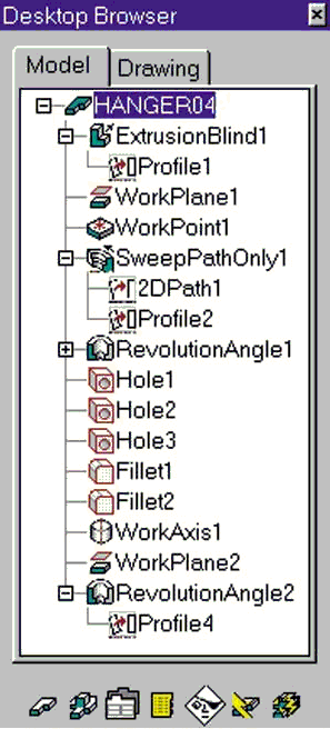
(11) Notice in the Browser window that the inserted part has an associated name and that the steps in creating the part are dull. This is because the part is not active. To make the part active, DLC on the 'Browser' part symbol. The part symbol and all the creation steps will go from dull to bright colors when the part is active.
(12) You've just imported a drawing that could have come from anywhere. Your AutoCAD window should look like the following.
[screenshot here of the Insert dialog box]
b. Have your engineer design team in Kenya forward you their 'large hinge' CAD file. (For our
purposes, go to my web site and download the Hinge2.dwg file.) Follow the same steps as in part (a) above.
c. Have the 'Metal Fabricators, Inc.' company forward their CAD files for the bolt and nut you
wish to use for your object. (Again, follow the same steps as in part a. above and import both
the Bolt2.dwg and Nut2.dwg files. Remember that the URL locations could be different for
each item imported.)
d. Your model space workspace should now have four parts displayed. Notice that only the
BS_PLATE2 part is active. ONLY one part can be active at a time. Using the Sketch View
icon selections and LC on part then selecting the Move option can provide the below layout.
[screenshot here of the Plate, Hinge, a nut and a bolt in the editor (MDT model mode screen)]
7. Now that you have imported the parts necessary to assemble your product, it is time to create two more
copies of the bolt and nut since your product requires three bolts and nuts. Create both part copies by:
a. RC on the part you wish to copy in the Browser window and then LC on Copy.
b. LC at the location you want to place the part and continue to LC until you placed as many copies of the part in your workspace as desired.
c. After you have created the last desired part, RC and LC on Enter.
d. Your drawing should now have eight (8) parts.
8. It is now time to assemble the object...
acad-atc.ic.polyu.edu.hk MDT, AutoCad (some Inventor) training at The Hong Kong Polytechnic University. Really good. See MDT nurb spline models like the 4WD and the Volkswagon for example. Full keystroke instruction. Worth printing some out.
Need to add this link to AutoCad 2D and 3D pages.
See interesting solid model 3D Building using multilines then region and extrude for the walls. Interesting solid stairs and solid roof construction method.
There is also an Inventor introduction and basic tutorials.
www.avatechsolutions.com/training/elearning/default.asp Go to eDemos for Windows Real Media demo of some new A2004 enhancements (and some A2002 enhancements). See also Tech Tips for AutoCad and *Mechanical* (which includes Mechanical Desktop and Inventor). Link repeated on AutoCad page.
www.cadonline.com/solutions/acadmdt/0100acadmdt/0100mdt.htm ## 400 Not Found 21June03 to 15July03 ## Making a simple part (a shifter fork) with workplanes at an acute angle. Emphasizes the need to keep Work Features as high as possible in the assembly tree to maintain flexibility to make subsequent changes. By Bill Fane of the British Columbia Institute of Technology. Origially appeared in Cadalyst January 2000. Excellent. For MDT4,5,6 (and presumably 2004).
acadmdt/mdt_tuts/knuckle/knuckle.html My local copy.
usa.autodesk.com/adsk/servlet/item?siteID=123112&id=2372223 Bill Fane extends the thinking on the shifter fork to show that the problems that could occur in work order and constraining that effects subsequent flexibility to make changes also impacts on your ability to use the supression feature (either just via the browser or using a spreadsheet). An AutoDesk tutorial. For MDT4,5,6 (and presumably 2004).
usa.autodesk.com/adsk/servlet/item?siteID=123112&id=2375129&linkID=610499 ## 400 Not Found 25Apr03 to 7Jul03 ##
Bill Fane explains use of spreadsheet (table) driven dimensioning (including an example of feature suppression) in detail with lots of screen shots of the dialog boxes. An AutoDesk tutorial. For MDT4,5,6 (and presumably 2004).
www.masterg.com/newsletter/winter2000/tips_mech-desktop.html ## 400 Not Found 5June03 to 15July03 ##
** Link seems broken -see my saved local copy below**
MasterGraphics Winter 2000 Newsletter. Short tutorial like tips with good small graphics. Need a local copy of this I think. Of particular interest was the AMPARTEDGE command that allows you to copy a series of edges to base a sketch to make a profile from (like when making the relief of a conrod to cut away to form the *I* beam cross section. Also they closed a profile with a cylinder edge.
They also advocate setting DISPSILH back to 0 to improve performance after you have finished constraining to a cylindrical edge (requires DISPSILH=1) for example.
acadmdt/mdt_tuts/mastergraphics/mastergraphics.html Local copy of these good tip/tutorials with good clear supporting screen shots (I called right again! -the main link has gone down).
www.leacar.com/leacar_main.htm LeaCar Consulting (MDT)
MDT tips and a good tutorial on rotating about an axis parametrically.
Use it as a basis to create large parametrically controlled assemblies with maximum variability. Good stuff but not for a beginner.
www.teknigroup.com/mdt2/pub/2D_3D.htm
Really good interactive 2D AutoCad to 3D MDT (non-parametric solid) tutorial. **Company bought out -No Link See my saved local copy below**
acadmdt/mdt_tuts/rocker/2D_3D.html Local file. Good tutorial. Get this file up and resize it so it fits on the left third of the screen and put MDT on the right. Short and informative.
Proper Balloon/Text Sizing in Mechanical Desktop 4 and 5 BOM.
In MDT 2 and 3, the balloon text size controls the size of the balloon, providing a non-standard balloon size. MDT 4(5,6 and presumably 2004) follows this same approach. However, version 4(5,6 and presumably 2004) also provides for a user defined balloon with text, utilizing a block with a text attribute. Instructions on using this technique along with a sample block utilizing a 0.375 inch balloon and 0.1875 inch text are located at: acadmdt/mdt_tuts/balloon/balloonfix.html Good stuff but maybe not for beginner.
kwik-mcad.scriptmania.com Kent Keller's site. Mainly VBA for MDT. Overview of ways to launch VBA in acadmdt/AutoCad. Look for for the 'Assembly Tree' program. It will dump the browser tree into Excel. It accesses the Xref paths.
www.cadalyst.com/solutions/mdt
Refers to at least two article/tutorials by Bill Fane. Part assembly and 3D constraining. Main points are:-
1. Making copy of a part in an assembly drawing by creating an instance (copy using unique mdt commands eg right-click on the part in the Browser, then select Copy) OR using the standard Autocad copy command (within MDT) is analgous to 'inserting a block' in vanilla Autocad. Likewise, you can right click in the Browser and Delete or use the AutoCAD Erase command to get rid of any unwanted instances.
Eternalising a part or referencing a part into an assembly drawing is analgous to the Xref in Autocad and the oft vaunted facility to edit an external part is fraught with danger if a standard part has been referenced into a number of other assemblies in the past.
2. Constaining parts together in an assembly can result in over constraining. MDT does not tell you that a constraint is redundent. The downside is when you want to make changes (the whole point of parametric drawing!) and you either can't do it or get unforseen chain effects. For a simple example, one face-face and two flush-flush brings two rectangular solids together with no degrees of freedom or you could use three line-line contraints or some permutation. Bill Fane was able to use eight contraints where the last five were redundant but happily accepted by MDT (this is the case up to MDT6).
For example, from about MDT3 a flush-flush and a (centerline) line-line was used to line up holes or place bolts. The insert was introduced to do these two together for efficiency. However some people will happily insert all the holes of a flange plate together when one hole insert and say (centerline) line-line of one other bolt hole (or perhaps an angle contraint) would be sufficent to remove all degrees of freedom. Gee you could lash out and do two inserts even though the face-face component of the second insert would be redundant. All the bolts will have to be inserted sure (I suspect arrays are a consideration in situations where large bolting patterns are required to be shown in place *See my tut attempt at this below).
acadmdt/mdt_tuts/boltpattern/boltpatterns.html A bolt pattern tutorial. Suit MDT4,5,6 (7?).
acadmdt/mdt_tuts/jeffhowardmdt6/helmet1.zip Helmet1
Local MDT6 zip file. Lofting. Download, unzip and open in mdt6+ then use the AmReplay command to see how a motor cycle helmet was created. ** It will not open in MDT4 **
www.cadenceweb.com/2000/0200/thirddimension0200.html An article with a good sketch and browser display that I would like to practice with.
acadmdt/mdt_tuts/sweepbracket/sweepbracket.html My local partial file (images below).
*Note: As an unrelated but useful extension I have uploaded a part and provide notes on how to externally reference in or copy in a part over the internet using AmCatalog and AmCopyIn. More notes on localising or copying in could be added but everything needed to get the Browse the Web - Open dialog box up and select a part and bring it in is provided.


acadmdt/sectionassem/sectionassem.html Section an assembly (not easy to do in Inventor) by Mike Maenpaa.
acadmdt/sectionassem/ShowInternalComponents.zip Sample MDT6 download (zipped 76kb).
Tutorial Links Only
![]()
www.tenlinks.com/cad/mcad/users/acadmdt/mdt10.htm Their 10 top MDT links.
www.tenlinks.com/CAD/mcad/index.htm MCAD articles.
www.tenlinks.com/CAD/MCAD/USERS/inventor/index.htm Inventor articles.
MDT And ACad Threads
Make 2D and 3D Threads Index of my spiral and helix thread related notes. Some involves instruction in use of Autolisp
See also acadalisptrng/index.html Index of AcadLispTrng folder with more tutorial content involving Autolisp.
acadthreads/caddigest_lisp_user_trng.html Some CadDigest AutoLisp user training by Bill Fane.
Useful overview of autolisp, short code examples and instruction on how to load and run your own or downloaded lisps. Includes introductory creation of your own menus, custom support folders, file paths and more. Intended for the complete beginner but some useful tips for the more experienced.
Displaying Plastic Closures The page that started me looking for threading options.
www.afralisp.com/tutor.htm Learn lots about using Autolisp at this top Namibian site. Excellent tutorials, refernces and sample applications all very well commented. See also links to people he holds in regard.
IRFANVIEW TUTORIAL. It's an excellent, small, and free/shareware photo editor at www.irfanview.com . An equally excellent tutorial is at
www.somewhere-in-time.net/tutorial/irfanview. From Neat Net Tricks. Use instead of PaintShop Pro or MS Paint.
MDT 3rd Party
www.cadalog.com/shareware/../ CADalog's AutoCAD Mechanical -> AutoCAD - Mechanical Desktop shareware and freeware. Saw a Hasco moldbase for MDT6 and a 'midplane' extruding program for Autocad just in the first page. Many more to look at.
www.abicad.com Input software for AutoCad and related family of products. Focuses on making the mouse perform more roles so less tool buttons are needed to be up. Includes the rewhell.arx tool for MDT reccomended in an Adesk Discussion forum posting. Duplicated in Drawing aids section of acad3rdparty page
Advantages Of MDT6 Over MDT5
acadmdt/adv_mdt6_over_mdt5.html A case for upgrading from MDT5 to MDT6 (as part of the AIS -AutoDesk Inventer Series).
See ..You would then get the freebie Inventor. While existing MDT6 owners will have to wait until MDT7 (eventually named MDT 2004) is released before they can upgrade and get the free Inventor. Because now when you upgrade Mechanical Desktop you get AIS (AutoDesk Inventer Series) which is Mechanical Desktop with Inventor tossed in. AutoDesk are very agitated about it being referred to as being given away. They want to be able to say there are 2000,000 seats of Inventor out there instead of the 20,000 purchased seats of Inventor and the 180,000 seats of MDT which is the reality.
Heard IV5.3 is a bit faster than IV5 (a new kernal!) but problems with IV5.3 reading IV5 files
(a new kernal!). Heard IV5.3 was just them converting IV5 to the new kernal with no substantial additional advances. Inventor has got to be the longest running beta program ever. I'll become a player when we upgrade to MDT7 (we are not subscribers) because then we will have 19 seats of Inventor like it or not.
Advantages Of MDT(7)2004 Over MDT6
Note this duplicates the MDT(7) 2004 section in MDT Page 2.
* Some new aspects to consider in MDT 2004 include:
- copy definition with keep/replace option.
- fastener sets get automatically constrained together (auto constraints for fastener sets). ie When you create a screw connection, the contraints are created for you.
- several dialog boxes enhanced/streamlined
- auto alert for xref changes
- several dialog boxes can be transparent and autohide/autorollup
You can drag the command line into the drawing area, right click on it, and 'ghost' it. you can then see your geometry underneath the command line. It gives you an extra couple of inches of screen.
(To bad all the fancy ghost features are not supported in hardware acceleration mode.)
The properties and and the new 'tool palette' commands can be nested along the side of the screen, and when you want to activate them, you just move the cursor over them and they open up. Very neat.
The biggest thing to get used to is the Icons are a bit different looking, so it takes a little time to adjust.
Another goody is the enhanced RMB treatment.
Surfacing:
The only information I can find is that there are no new surface tools in MDT 2004. The only difference in Inventor 7 is that surfaces can now be used to split each other and then one side of split surface deleted. (Kind of a two step surface trim - very tedious.)
* AUTOCAD 2004 TIPS: I assume this applies to MDT2004)
AutoCAD 2004 adds a few new tricks to the right-click menu:
In Windows Explorer or File menu dialog boxes (Open, Save, etc.), you can preview all drawings in a folder simultaneously - in the file list, right-click and select View/Thumbnails.
Right-click on the Command line and select Recent Commands to access the last five commands you've used.
Nurbs Surfaces In MDT
IGES and NURBS Surfaces in AutoCAD
NURBS splines are standard object types in R2000+/R14/R13. Some confusion arises as to the nature of splines and surfaces. AutoCAD does not support NURBS surfaces, nor will IGES translate NURBS surfaces into AutoCAD without conversion. NURBS surfaces will be translated as either Polyface meshes or NURBS spline wireframes. There will be a great deal of accuracy lost in a model if NURBS surfaces or splines are converted into polylines or polyface meshes. **Mechanical Desktop will accomplish the translations accurately, but standard AutoCAD will not.
Note: The last sentence above refers to taking a nurbs surface (say made in Rhino ..argueably the best dedicated surface modeller around) into MDT.
but, overheard on the CADChat forum..
Q: How does Rhino work with MDT at your shop? Do you use Rhino surfaces imported into MDT?
A: No, we go the other way. We design in MDT and the blocks are STEP'd (ie .stp, .step) out of MDT into Rhino to be surfaced.
(AJ Note in MDT4 Edit->Export leads to five choices ..got iges but two including STEP and VDAFS are grayed out in the insert pull down!? It seems Data Exchange was sold as an add-on for Desktop 4.)
Q: Do you use a manufacturing program with Autodesk stuff?
A: We use WorkNC for our cutter paths, But the surfacing comes from Rhino, not MDT. WorkNC is easy to learn. I have taught guys to use it in a day.
MDT Commands And Systems Variables
My collection of easily readable, scrollable and printable listings of commands and system system variables. I'm not trying to reinvent the wheel. Information in this convenient form is just not provided in the box with the software, the Help files or eventhe Autodesk website.
Note the command SYSVAR. Selecting options ? then * causes the AutoCad system variables to page down on screen so you can at least see something that might trigger your memory or look like what you want. I had hoped that AM* or something would list the MDT system variables but no such luck. If someone knows how to similarly list the MDT system variables at the command line please let me know.
acadmdtsysvar.html Local html file of documented MDT4 system variables with explanations.
technology.calumet.purdue.edu/met/tickoo/students/acadmdt/mdt.htm Sham Tickoo. Three pdf chapters of his MDT5 book (** See duplicated fuller content listing in MDT Links section for the chapters) and three Appendices. AppendixA is the Toolbars detailed, AppendixB is the System variables and AppendixC is the Commands. Excellent. Print the lot. Applies to MDT5,6 (and presumably 2004). Majority still applies to MDT4.
acadmdt/tickoo/Appendix-C.pdf Local file of the MDT5 Commands (pdf 90kb).
acadmdt/tickoo/acadmdt5cmds.html Local file of the MDT5 Commands with some notes (html 34kb).
acadmdt/tickoo/Appendix-B.pdf Local file of the MDT5 System Variables (pdf 85kb).
acadmdt/tickoo/acadmdt5sysvar.html Local file of the MDT5 System Variables with some notes (html 31kb).
acadmdttips.html#undocumented My section on what I understand to be undocumented commands and system variables on the MDT Tips And Memory Joggers page. I deem it undocumented if a command or system variable is accepted at the command line but there is nothing in the Help files referring to it.
Exploring Sheetmetal Work
acadsheetmetal/index.html Awaiting a home after evaluation. At present this call is in Autocad, Customizing, 3D and MDT.
Using VBA For CAD/CAM
www.cadalyst.com/solutions/trenches/0703vb CADALYST - July 2003 From the Trenches. Article on using VBA for CAD/VCAM. Code downloadable. To quickly and simply generate 2D and 3D tool paths for CNC mills. (Good for AutoCad and MDT -aj).
acadmdt/vbacam/vbacam.html Local version.
acadmdt/vbacam/index.html Index of vbacam folder. Lists what I have put together about using the VBA code from Cadalyst.
www.matweb.com For materials information to match up to the blanks that are in the Materials Dialog box of MDT6.
*See also CNC Zone forum and associated links at the bottom of the Forums section.
ETransmit ToBackup MDT/ACad
ETRANSMIT (File->eTransmit) introduced with A2000i as well as Light, MDT and related verticals is a command I've ignored because it was touted as part of 'collabrative' design. But I've had problems moving MDT files around my computer and my employer's network and Mark Middlebrook's Cadalyst articles on eTransmit and the earlier Pack 'n Go Bonus/Express utility has clarified the value of eTransmit for a file management, backup and archieving role quite independently of 'sending files as email attachments and converting to dwf' which was the marketing spin.
acadmdt/etransmit/index.html Index of articles and experiences using eTransmit and Pack 'n Go.
**REVIEWED TO HERE.**
MDT Forums
The following forums have MDT sections (duplicated in the AutoCad page).
www.eng-tips.com -General Engineering Programs AutoCad, MDT, Spreadsheets, VB and VBA.
Autodesk Discussion Groups User forums for each Autodesk product. MDT is under 'MCAD'. Autodesk 'moderated' which means posters have to choose their words carefully if being critical of Autodesk or risk having the posting moved/removed or being put on a kill list.
Google Autodesk Discussion Groups User forums for each Autodesk product. MDT is under 'MCAD'. Apparently the same postings as would appear in the AutoDesk Discussion Groups but maybe a bit behind. But where Adesk where listing the last 3 mths of postings, Google is listing the postings back to the beginning of the package. For example Adesk last 3 mth of MDT4 is about 18 topics while Google lists 780 topics going back to the early days of MDT4, similarly there are approx 400 ADesk MDT5,6 topics in last 3mth versus over 7000 MDT5,6 topics in Google. Figures from Arpil 2003.
www.cadchat.com CADChat. AutoCad/acadmdt/Autodesk and other sections such as IntelliCad or MicroStation for example. Started by experienced practioner (with real day job). Supported by Kenny Rammage of www.AfraLisp.com. Easy to navigate. Good People. Recommended. Give DanB a bit of support in the MDT Forum.
www.d3technical.com/forum/phpBB2 Friendly small company forum. Separate MDT, Mechanical and Autocad. 2004 forums established. Management input.
communities.msn.com/AutoCADusersforum/messageboard.msnw MSN AutoCad Forum. Separate AutoDesk product/release boards. Fair activity. Poster tips and tricks, secret commands, bug list. Inactive MDT. Need a .NET Passport (which I would not do) but you can still read posts. * Apparently they will accept a Hotmail email address instead of a .NET Passport.
www.CADTutor.net/forum David Watson's (ex Uni of Greenwich) CADTutor AutoCad and other forums. Use to have MDT section (no posters) but now only has Solid Modelling & Rendering' section.
cnczone.com CNC Zone. Scroll down for 'Autocad and Mechanical Desktop' forum. Good.
www.tahlcam.com/download.html
From a poster. An interesting CAD/CAM plug-in for A2002 (A2004 comming soon). TahlCAM 2002 provides the CNC machinist with a set of tools that gives complete control over cutter movement.
Free download with no time limit or license. The only limitation is a 500 line post length. AutoDesk Authorised Developer.
MDT (AIS) Hardware
I learnt MDT4 (came with AutoCad 2000) on a PII/400Hz with 64Ram, a cheap video card with 2Meg of Ram and Win 95.
I made a minimal number of parts, and an assemblies consisting of only two or three subassemblies. By suppressing fillets for example and using xrefs most of the good practices were employed out of necessity that would be practiced in a production enviroment where more expensive system resources is demanded by proportionately greater project needs. It's just a matter of scale.
It was my habit when using MDT4 to be on the internet, have up my editor (Homesite) up to take odd notes and, when needed, also get up MS Paint (or PaintShop Pro) or Excel and Windows Explorer. The system dealt with this, if slowly, and sent me messages to say enough was enough and would lock up if I did not back off. You learn to save regularly.
When my employer moved to P4's with Win 2000 and MDT6, I put bought a video card with 8 Meg on it for $30 and 128 Meg of RAM for $55 off a guy selling from a tresle table in the local shopping center.
So with a PII/400Hz with 190Ram and a cheap video card with 8Meg of Ram and with MDT6 on Windows 2000 I can now have Rhino3D up as well as everthing else I normally have up. And I start planning again for my next big upgrade.
acadhardware.html MDT - Inventor Hardware
Collection of comments and info to get ready to upgrade for MDT2004 and Inventor7.
Adobe PDF Related
You can't escape Adobe pdf files although I try to most of the time.
Is it possible to save a rendered MDT model to pdf?
Either rendered or shaded, in both cases you have to print to pdf. Whatever you can get to a printer, you can get to a pdf, as soon as you have installed a program like Destiller, PDF Writer, or any of the share/freewareprograms. Leo Laimer Apr/11/03
www.adobe.com/products/acrobat/access_simple_form.html An adobe page that allows you to convert a pdf file with a url to html. Images are not processed. Todate I found I could not save the html translation but I'm still learning.
pdf_use/use_alt_printscrn/use_alt_printscrn.html PDF References in Education.zip from AutoDesk University Dec 2002
Summary of portion of a presentation by a trainer presenting at AutoCad University in Dec 2002 and notes of my own. It addresses use of MS Paint for screen captures and capturing text and images from a pdf document.
www.mossdesigns.com/pdffiles.htm Creating a PDF file from an Autodesk file.
A tutorial bt Elsie Moss describing how to convert Autocad, MDT or Inventor files for example to pdf format using software you can download free from Adobe.
pdf_use/pdf_from_adesk/create_pdf_from_adesk_file.html
Locally held file of Elsie's tutorial.
www.mossdesigns.com Elsie Moss's homepage.
www.satelephone.com/~adee/aaa ** 26 April 2003. This url gives a better idea of whats happening at this site. Some good links, tips and articles that refer to pdf (and Power Point ie wmf) from an Autocad users perspective. Heavy use of pdf on the site. (link duplicated here from Miscellaneous section of Customising page)
Displaying Plastic Closures Communicating design intent.
Contact: Aussie John wpsmoke@yahoo.co.uk